
TM
11-6130-243-14-2
FUNCTIONING OF EQUIPMENT
through the jumpers to each parallel-connected
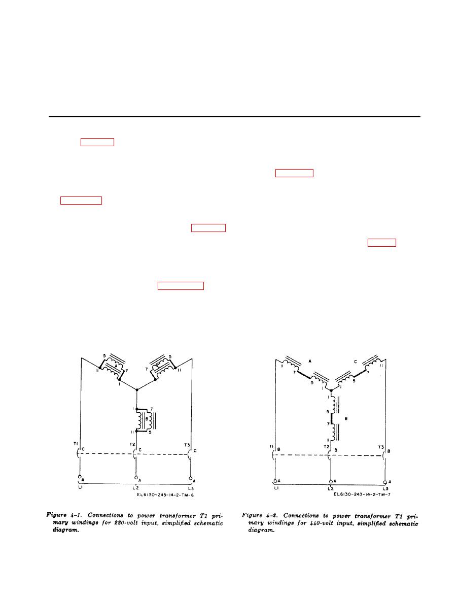
4-1. Input Power
pair of primary windings in each leg of the wye.
a. The power supply is designed to operate
4-2. Output Circuit
from either 220- or 440-volt, 60-Hz, 3-phase
(figs. FO-2 and 4-3)
power mains. Jumpers are used to provide for
correct connection of the power mains to the
The output circuit includes the secondary wind-
primary windings of input power transformer
ings of power transformer T1, diode rectifiers
T1. Figures 4-1 and 4-2 are simplified sche-
CR1 through CR6, rectifier assembly CR7, cap-
matic diagrams that show how the primary
acitors C1 and C2, load resistor R2 and filter
windings are wye-connected to the power mains,
r e a c t o r L1. Secondary windings of T1 are
Refer to the complete schematic diagram (fig.
connected in a delta configuration as shown in
FO-2) while studying the two simplified sche-
the simplified schematic diagram (fig. 4-3). The
matic diagrams.
alternating current (ac) output voltage from
b. When the power supply is arranged to op-
the secondary windings of T1 is converted to a
erate with 220-volt input power, jumpers are
pulsating direct current (dc) voltage by full-
connected between specific terminals as shown
wave rectifiers CR1 through CR6. Rectifier as-
by the short heavy lines in figure 4-1. The
sembly CR7 suppresses transients in the input
primary windings of transformer T1 are thus
and output lines thus protecting diode rectifiers
parallel-connected into a wye configuration,
CR1 through CR6. The dc pulses are applied
W h e n the lNPUT POWER circuit breaker
to filter reactor L1, load resistor R2, and filter
switch (CB1) is at ON, input power is routed
capacitors C1 and C2. Resistor R2 serves a
from the C terminals of the circuit breakers

