
TM 11-6130-243-35
TM6130-243-35-1
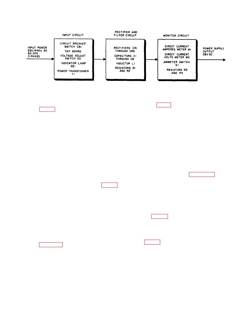
Power Supply PP-4606/G block diagram.
(not shown on fig. 1-2) to each parallel-con-
nected pair of primary windings in each leg of
the wye. VOLTAGE ADJUST switch S2 con-
a. The power supply is designed to operate
trols the voltage in the secondary windings of
from either 220- or 440-volt, 60-cycle, 3-phase
transformer T1 by controlling the number of
power mains. To provide for correct connec-
turns energized in the primary windings. (En-
tion of the power mains to the primary wind-
ergized turns decrease and secondary winding
ings of input power transformer T1, a tap
voltages increase as switch S2 is turned clock-
board is provided on the rear of the power
wise.)
supply. Wire links are connected between
specific terminals on the tap board, depend-
c. When the power supply is arranged to
operate with 440-volt input power, wire links
ing upon the voltage of the power mains from
which the power supply is to be operated. Fig-
are connected between a different group of
ures 1-2 and 1-3 are simplified schematic dia-
specific terminals on the tap board as shown
by the short heavy lines in figure 1-3. The
grams that show how the primary windings
are wye-connected to the power mains. Refer
six primary windings of input transformer T1
are now series-connected into a wye configu-
to the complete schematic diagram (fig. 4-4)
while studying the two simplified schematic
ration. When circuit breaker switch CB1 is at
diagrams. For simplicity, VOLTAGE AD-
POWER ON, input power is routed from the
breaker
440-volt terminals of the circuit
JUST switch S2 is not shown on the simplified
schematic diagrams; however, assume that it
through the wire links on the terminal board
is at the fully clockwise position (HIGH) for
and the VOLTAGE ADJUST switch (not
the discussions in b and c below.
shown on fig. 1-3) to each series-connected
pair of primary windings in each leg of the
b. When the power supply is arranged to
wye.
operate with 220-volt input power, wire links
are connected between specific terminals on
the tap board as shown by the short heavy
lines in figure 1-2. The six primary windings
a. The output circuit includes the three sec-
of input transformer T1 are thus parallel-con-
nected into a wye configuration which corre-
ondary windings of power transformer T1,
sponds to the wye configuration of the input
diode rectifiers CR1 through CR6, surge-sup-
power mains. When circuit breaker switch
pressor capacitors C3 through C8, bleeder re-
CB1 is at POWER ON, input power is routed
sistors R1 and R2, choke L1, and filter capaci-
from the 220-volt terminals of the circuit
tors C1 and C2. The secondary windings of the
breaker through the wire links on the tap
board and the VOLTAGE ADJUST switch
power transformer are connected in a delta

