
TM 11-6130-247-14-1
current and a specific voltage that is not to be
exceeded, proceed as follows.
a. Turn front panel VOLT ADJ and CUR
ADJ coarse and fine controls fully counterclock-
wise and set power supply POWER switch S1
to off.
b. Determine the limits of voltage and current
to be supplied by the power supply. For example,
constant voltage of 28 volts dc with current not
to exceed 1.5 ampere dc.
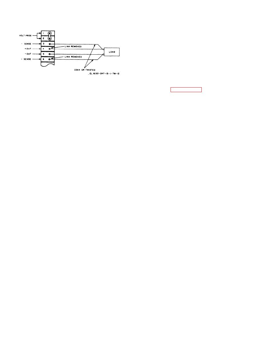
Figure 2-5. Power Supp!y PP-3940A/G, connections for
c. Be sure that terminal board links are con-
remote sensing.
nected as stated in paragraph 2-5a.
d. Connect load to front panel terminals.
leads from terminals 3 and 6 should be
e. Set power supply POWER switch to ON.
either a coaxial pair or twisted pair
in order to minimize stray pickup,
f. Set the not to exceed value (either current
which might result in power supply in-
or voltage), using the front `panel coarse and
stability.
fine controls and meter. (For the example given
in b above, turn the CUR ADJ coarse and fine
d. Set POWER switch S1 to ON and turn
front panel CUR ADJ coarse and fine controls
controls for a reading of 1.5 ampere on ammeter, )
fully clockwise.
g. Set the constant value (either current or
voltage) using the f rent panel coarse and fine
e. Adjust front panel VOLT ADJ coarse and
controls and meter. (For the example given in
fine controls for required. constant voltage out-
b above, turn the VOLT ADJ coarse and fine
put.
controls for a reading of 28 volts on voltmeter. )
2-12. Power Supply Setup Procedures When
NOTE
Specific Values of Voltage and Current
When the power supply is set up in
Are Required
this manner, there may be a flickering
When power supply output requirements specify
between VOLT MODE and CUR MODE
both a constant voltage and a specific current
lamps when operating at the not to ex-
that is not to be exceeded, or both a constant
ceed value.
2-6

