
TM 11-6130-247-14-1
CHAPTER 4
FUNCTIONING OF EQUIPMENT
4-2. Block Diagram Analysis
4-1. General
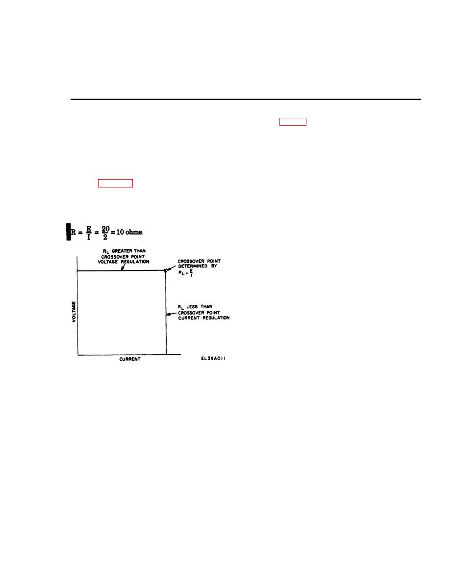
a. The power supply is a variable-output, voltage
a. Input power is applied to the primary side of
regulated, current-regulated dc supply. The charac-
transformers T1 and T2. The secondary voltage of T1
teristic of this type of regulated power supply
is applied to a full-wave, solid-state rectifier with
exhibits a crossover point at which the supply switches
capacitor filtering. The rectified voltage is applied to a
from voltage regulation, indicated by the front panel
dc switching-type preregulator which breaks up the dc
VOLT MODE indicator being lit, to current regulation,
voltage into pulses. The output voltage is determined
indicated by the front panel CUR MODE indicator
by the relation of on-time to off-time of this switch.
being lit. Figure 4-1 indicates this crossover point as a
The series switch arrangement is a very efficient
function of the preset value of the front panel VOLT
device, but it has a slow response time to any detected
ADJ and CUR ADJ controls. For example, setting the
errors in the output. The response time is increased by
front panel controls for 20 volts dc and 2 amperes and
providing a linear series passing network which
Using Ohm's Law
provides instantaneous correction for output error.
b. Under normal conditions, a short circuit across
the output will drive the series regulator into current
mode operation, holding the short circuit current to
the preset value of the CUR ADJ controls. However, if
a series passing stage in the series regulator is shorted,
in addition to the external short circuit, the combina-
tion will produce a damaging amount of current
through the preregulators. An overcurrent protection
network is provided to sense this condition and will
short out the preregulator circuitry, relieving the pre-
regulator elements of all current.
c. The ability of the voltage and current regulating
circuitry to detect errors is dependent upon the ability
of the reference supply to provide precise voltages to
the regulating circuitry. The regulating circuits are
differential amplifiers which depend on a constant
voltage being supplied to one side of the circuit to
Figure 4-1. Power Supply PP-3940A/G, crossover characteristics.
detect errors in the output.
4-3. Detailed Circuit Analysis
more, the power supply will regulate the output
voltage at 20 volts dc and the VOLT MODE indicator
a. Rectification and Preregulution. The 115-volt
will be lit. If the load resistance is less than 10 ohms,
ac, single-phase, 60- to 400-Hertz input is applied
the power supply must produce more than 2 amperes
through POWER switch S1 and fuse F1 to pri-
of current to regulate the output to 20 volts dc. At this
mary of transformers T1 and T2. The secondary
point, the VOLT MODE indicator extinguishes, the
of T1 is connected to full-wave rectifier
CUR MODE indicator lights, and the current is regu-
lated to the set value of 2 amperes.
4-1
Change 1

