
TROUBLESHOOTING
Section I. GENERAL TROUBLESHOOTING TECHNIQUES
ments in this equipment only as spec-
ified. When measuring voltages, use
Troubleshooting at general support and de-
tape or sleeving to insulate the entire
pot maintenance levels includes all the tech-
test prod except the extreme tip. A
niques outlined for organizational mainte-
momentary short circuit can ruin a
nancse, and any special or additional techniques
transistor. Use resistor and capacitor
required to isolate a defective part. Para-
color codes (fig. 7-1 and 7-2) to find
the values of the components. Use the
ing procedures to be used at the general sup-
schematic diagram (fig. 7-3) to find
port level.
the normal voltage readings, and com-
pare them with the readings taken.
cedures
(2) Troubleshooting chart.
The trouble
symptoms listed in the chart (para
a. General. The first step in servicing a de-
tective power supply is to localize the fault.
a component part.
Localizing means tracing the fault to a defec-
(3) Intermittent troubles. The possibility
tive stage or circuit responsible for the ab-
of intermittent troubles should not be
normal condition. The second step is isolation.
overlooked. This type of trouble, if
Isolation means locating the defective part or
present, often can be made to appear
parts. Some defective parts, such as burned re-
by tapping or jarring the equipment.
sistors, arcing, and shorted transformers, can
Check the wiring and connections of
be located by sight. smell, and hearing. Most
the PP-3514/U.
defective parts must be isolated by voltage
measurements.
b. Localization. Power Supply PP-3514/U
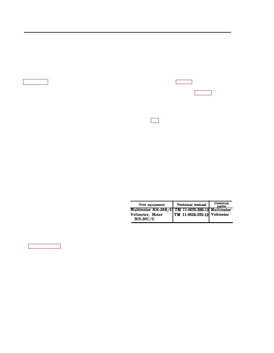
The following chart lists the test equipment
is composed of one unit. The first stop in trac-
required for troubleshooting Power Supply PP-
ing trouble is to localize the trouble to a stage
3514/U, and the associated technical manuals
or circuit, and then to isolate the trouble in
and assigned common names.
that stage or circuit by voltage measurements.
(1) Voltage measurements. This equip-
ment is transistorized.
Observe all
precautions given to prevent transis-
tor damage. Make voltage measure-
Section Il. TROUBLESHOOTING POWER SUPPLY PP-3514/U
Caution: Do not attempt removal or replacement of parts before reading the instructions
power supply from its case. Connect the test
2-4. Test Setup
equipment as specified for each particular test.
Bench tests of the power supply require con-
nections to an ac power source and various test
2-5. Localizing Troubles
equipment. The ac power source must be con-
a. General. The procedures given in the
nected to the power supply for all dynamic-
troubleshooting chart (d below) are outlined
ervicing procedures; the test equipment con-
for localizing troubles to a stage within the
power supply. The parts locations are indicated
nections vary from test to test. Remove the

