
TM 5-1730-245-14
SECTION II. REPAIR PARTS, TOOLS, SPECIAL TOOLS, TEST, MEASUREMENT, AND DIAGNOSTIC
EQUIPMENT (TMDE), AND SUPPORT EQUIPMENT.
4.4 Common Tools and Equipment. For authorized common tools and equipment, refer to the Modified
Table of Organization and Equipment (MTOE), CTA 50-970, or CTA 8-100, as applicable to your hydraulic
power supply. General Mechanics Tool Kit, item 5, Section m, Appendix B, and Shop Equipment, Automotive
Maintenance and Repair: Organization Maintenance, Common No. 1, less power, item 6, Section III, Appendix
Section III, for special tools and test equipment. Special tools, TMDE and support equipment for the hydraulic
power supply are also contained in Repair Parts and Special Tools List TM 5-1730-245-24P.
4.6 Repair Parts. Refer to Appendix I for mandatory replacement parts listing Repair parts are listed and
illustrated in Repair Parts and Special Tools List TM 5-1730-245-24P covering maintenance for this equipment.
SECTION III. SERVICE UPON RECEIPT
4.7 GENERAL. Visually check the exterior of the hydraulic power supply for any apparent damage such as
large dents, broken latches, loose or missing hardware, etc
.
4.8 PREPARATION FOR USE.
a. Remove the two side panels (8, fig 1-2) and the front radiator panel (5, fig 1-2). These panels are
held in place by two 1/4 turn fasteners (7, fig 1-2). Store these panels near the hydraulic power supply The
panels are to remain off during engine operation.
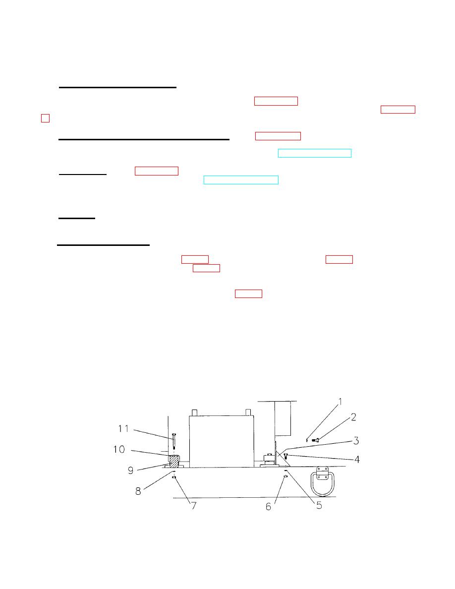
b. Remove the engine retaining wooden spacers (9, fig 4-4). A steel bracket (3) is bolted to the front of
the engine and to the base to retain the engine during shipment. Remove the two lockwashers (1) and screws
(2) holding the steel bracket (2) to the engine and the two bolts (4), lockwashers (5) and nuts (6) holding the
steel bracket (3) to the base. Remove the steel bracket (3). A steel strap (10) and wooden spacer (9) are used
to retain each of the two rear shock mounts. Remove the two bolts (11), lockwashers (8) and nuts (7) holding
the wooden spacers (9) and remove the wooden spacers (9). The steel straps (10) may be left In position on
the rear shock mounts. Save the wooden spacers (9), steel bracket (3), bolts (11 and 4), nuts (7), and screws
(2) for use in preparing the hydraulic power supply for reshipment.
Figure 4-4. Engine Retainers..
4-7

