
TM 5-1730-245-14
5.7 HYDRAULIC VALVE ASSEMBLY - REPLACE.
THIS TASK CONSISTS OF: a. Removal
b. Installation
INITIAL SETUP
Tools:
Equipment Condition:
Tool kit, General Mechanics (item 5, Section III, Appendix B).
Side panels (8, fig. 1-2) removed.
Shop Equipment Automotive Maintenance and Repair:
Battery disconnected. Refer to paragraph 4.19.
Organizational Maintenance, Common No. 1,
Cabinet top cover removed. Refer to paragraph 4.16
less power, (item 6, Section III, Appendix B).
Drain hydraulic fluid tank. Refer to paragraph 4.3.
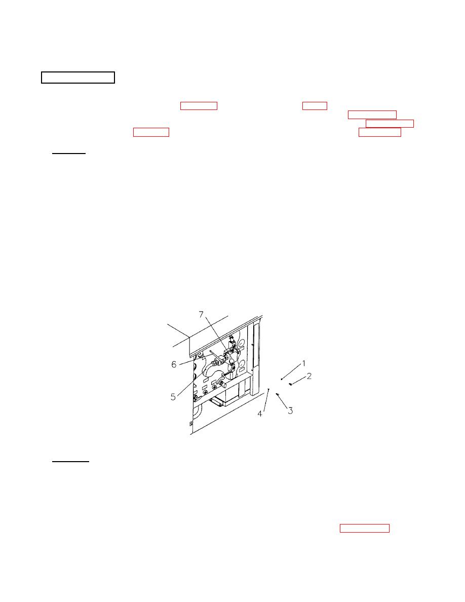
a. Removal, Refer to figure 5-4
1) Disconnect and plug the four fluid lines (5) attached to the hydraulic valve assembly (7).
NOTE
Make note of the relative position of the index marks on the valve stems and on
the valve handles The two smaller valves have the marks aligned and the larger
valve has the handle displaced 45 degrees counterclockwise. The index marks on
the valve bodies indicate through flow when they are aligned longitudinally with the
valve body
2) Remove the center screws (3) and flat washers (4) In the valve handles (6) and remove the three
valve handles (6).
3) Supporting the hydraulic valve assembly (7) from underneath, remove the two screws (2) and
lockwashers (1) holding the hydraulic valve assembly (7) to the panel and withdraw the hydraulic
valve assembly from above.
Figure 54. Hydraulic Valve Assembly.
b. Installation. Refer to figure 5-4.
1) Install the hydraulic valve assembly (7) on the panel and secure with lockwashers (1) and screws (2).
2) Install the valve handles (6) in their original positions and secure with washers (4) and screws (3)
3) Connect the fluid lines (5) and tighten connections
4) Install top cover. Refer to paragraph 4 16 Fill the hydraulic fluid tank Refer to paragraph 4.3.
5-9

