
TM 5-1730-245-14
5.9 HYDRAULIC RELIEF VALVES - REPLACE.
THIS TASK CONSISTS OF: a. Removal
b. Installation
INITIAL SETUP
Tools:
Equipment Condition:
Toolkit, General Mechanics (item 5, Section III, Appendix B)
Side panels (8, fig. 1-2) removed.
Shop Equipment Automotive Maintenance and Repair:
Battery disconnected. Refer to paragraph 4.19.
Organizational Maintenance, Common No. 1, less power
(item 6, Section III, Appendix B).
General Safety Requirements:
Material/Parts Required
Preformed Packing, Hydraulic (O-rings),
WARNING
items 1 and 2, Appendix I.
Hydraulic fluid, item 7 or 8, Appendix E.
Do not use near heat or open flame.
Hydraulic oils are toxic and flammable.
Area should be well ventilated DO NOT SMOKE.
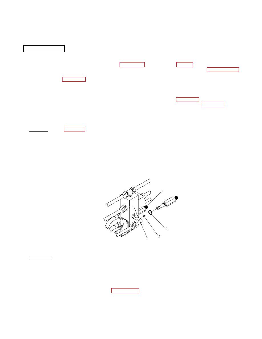
a. Removal. Refer to figure 5-6
NOTE
The hydraulic control manifold need not be removed In order to remove or install
the hydraulic relief valves
1) Remove hydraulic relief valve body (1) from the hydraulic control manifold (4).
2) Remove preformed packings (2, 3) and discard.
Figure 5-6. Hydraulic Relief Valves.
b. Installation, Refer to figure 56.
1) Install preformed packings, hydraulic (O-rings) (2 and 3), to relief valve Apply a coating of hydraulic
fluid to the valve stem and threads.
2) Insert the valve (1) in the hydraulic control manifold (4) and torque to 12.0 ft. lb. (16.27 Nm).
3) Fill the hydraulic fluid tank Refer to paragraph 4.3.
5-11

