
TM 55-1730-229-34
AG 320A0-MME-000
TO 35C2-3-473-2
TM 1730-34/1
an operator-activated mechanical lever
the control twist grips. The grips have
connected to the brakes on a cable. The
a motorcycle type accelerator that can
brakes are standard, automotive-type
be actuated from either side of the tow
drum units using replaceable brake
bar. The grips are spring loaded to a
shoes.
neutral, no-propulsion position.
The
grips rotate in either direction, one
10-1.1.
WHEELS AND TIRES.
way controlling forward direction and
speed, and the other way reverse direc-
a. Remove wheel assy, refer to, TM
The controller con-
tion and speed.
55-1730-229-12.
tains an emergency dead-man switch that
must be depressed to operate the speed/
b. Replace damaged tire, wheel and
Release of the
direction controls.
valve.
switch disconnects all power to the
traction motor. A mercury switch is in
c. Install wheel assy refer to TM
the same line as the dead-man switch.
55-1730-229-12.
The mercury switch opens the power sys-
tem supply when the tow bar is raised to
approximately 60 degrees or more from
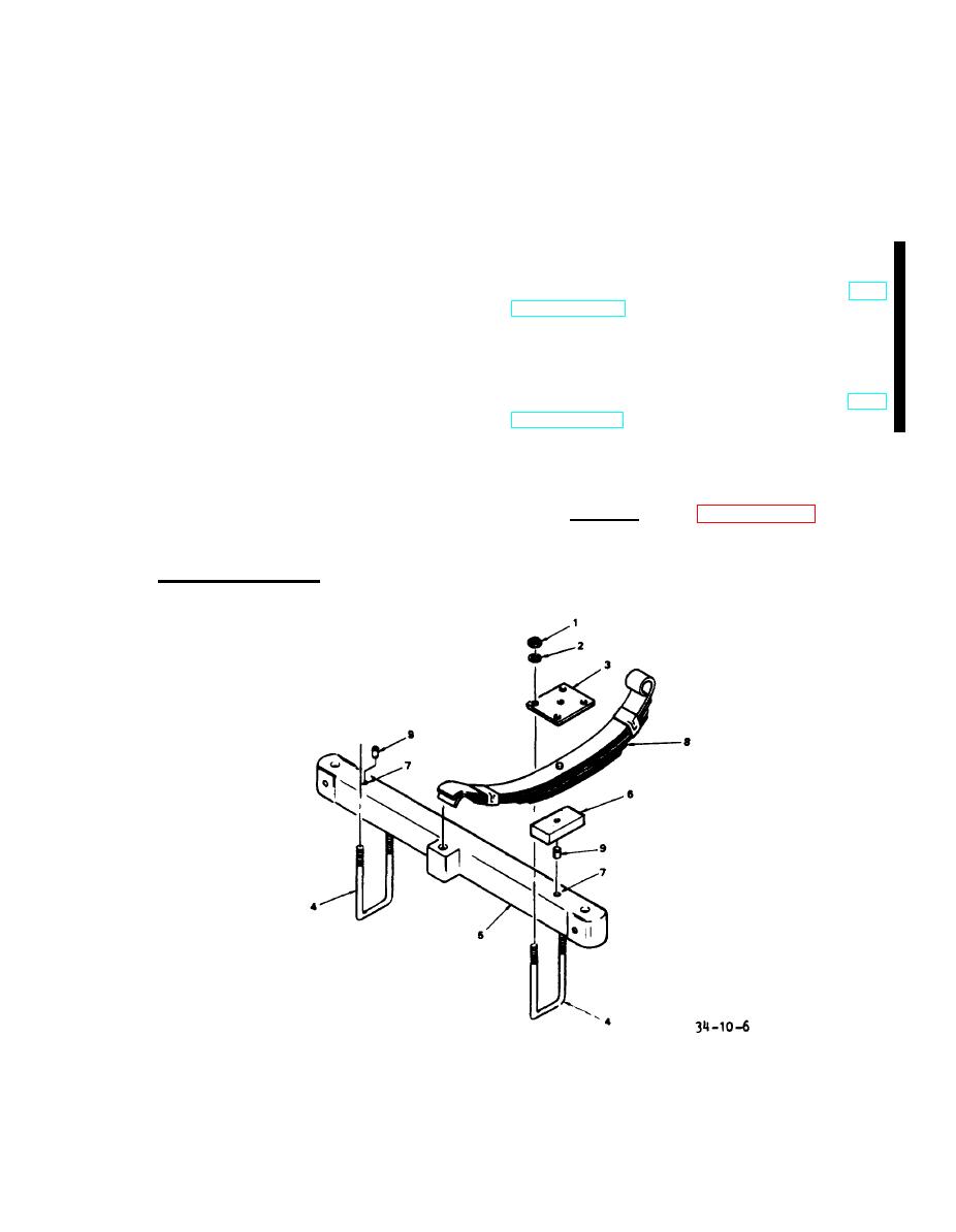
FRONT AXLE ASSEMBLY.
10-2.
horizontal. The assembly also incorpo-
rates an indicator light with a press-
a. Remove. (See figure 10-6.)
to-test feature that is illuminated when
the propulsion motor clutch is engaged.
(1) position AGPU on level sur-
face. Place chocks against rear wheels
h. Brake Assembly. The AGPU uses
and apply parking brake.
rear-wheel brakes that are controlled by
7. ALIGNMENT HOLE
4. U-BOLT
1. MOUNTING NUT
2. WASHER
5. FRONT AXLE (BEAM)
8. SPRING
3. PLATE, UPPER
6. SPACER
9. ALIGNMENT PIN
Figure 10-6.
Front Spring Assembly
10-7
Change 1

