
TM 3-4240-302-30&P-5
2-7. POWER DISTRIBUTION UNIT (CONT).
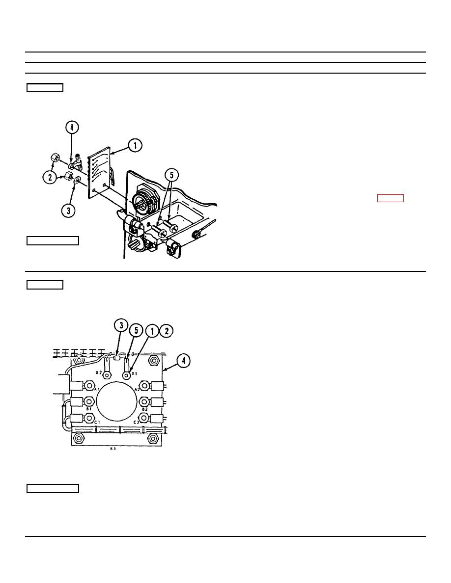
LOCATION
ITEM
ACTION
REMOVAL
Panel
Printed circuit boar d A5
1.
Remove two nuts (2), washer (3), tiedown strap
(4), and two screws (5). Note orientation of
tiedown strap (4).
2.
Unsolder and tag wires from printed circuit
board A5 (1).
3.
Remove printed circuit board A5 (1).
1.
Connect and solder wires to printed circuit
board A5 (1). Refer to wiring diagram (p. 2-39).
2.
Position printed circuit board A5 (1) on
bracket, and install screws (5).
INSTALLATION
3.
Install tiedown strap (4) and nut (2) on one
screw (5). Install washer (3) and nut (2) on the
other screw (5).
REMOVAL
Power Relay
Diode CR5
1.
Remove nuts (1) and washers (2).
CAUTION
Apply heat sink pliers to leads of diode when
unsoldering. Excessive heat will damage the
diode.
2.
Remove diode CR5 (3) from relay K1 (4).
CAUTION
Diodes must be connected properly or
circuitry damage will result. Observe the
banded end of the diode.
CAUTION
Apply heat sink pliers to leads of diode when
soldering. Excessive heat will damage the
diode.
INSTALLATION
1.
Solder terminal lugs (5) on diode CR5 (3).
2.
Install diode (3) between terminal X1 and X2 of
the relay K1 (4). Ensure that the band end is
installed on terminal X2. Secure with washers
(2) and nuts (1).
2-36
