Home
Download PDF
Order CD-ROM
Order in Print
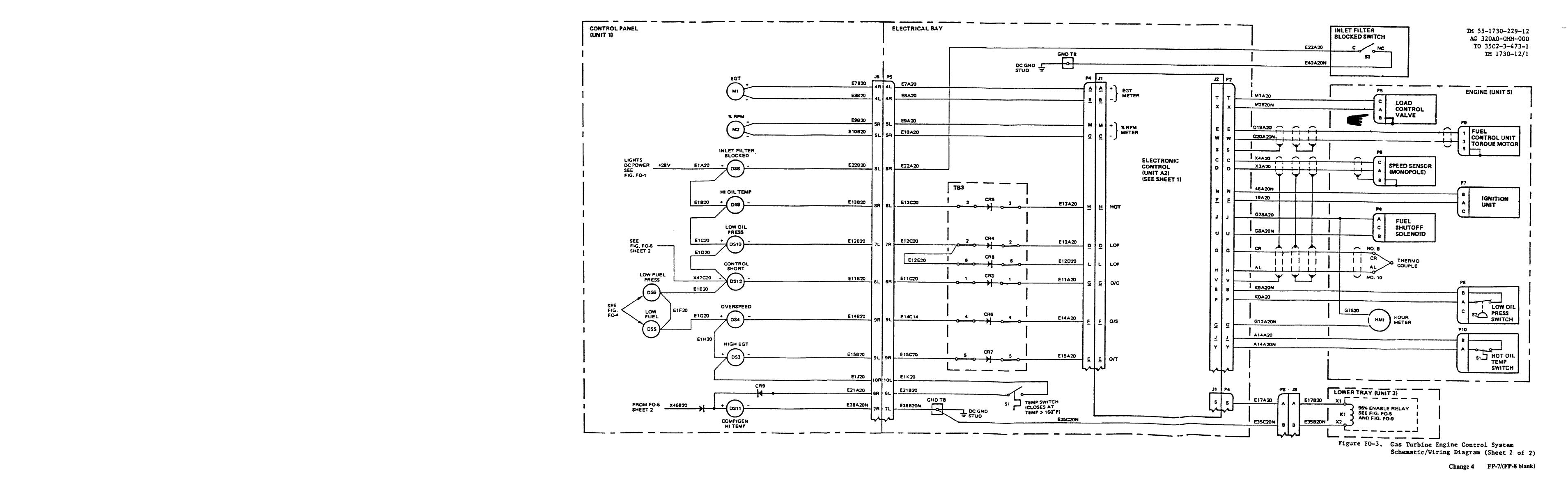
Figure FO-3. Gas Turbine Engine Control System Schematic/Wiring Diagram (Sheet 1 of 2)
Figure FO-4. Fuel Indication Control System Schematic/Wiring Diagram
TM-55-1730-229-12 Power Unit Aviation Multi-Output GTED Electrical Hydraulic Pneumatic (AGPU) Wheel Mounted Self-Propelled Towable Manual
Page Navigation
473
474
475
476
477
478
479
480
481
482
483