
TM 11-6130-247-14-1
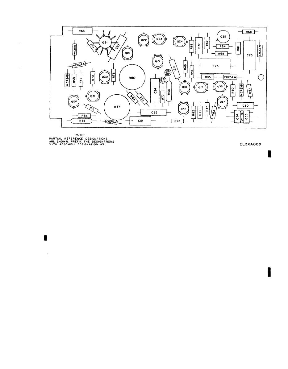
Figure 5-3. Power Supply PP-3940A/G, Component Board A3, Parts Location Diagram.
h. Connect variable power transformers to the 115-
ters R53A and R53B and VOLT ADJ coarse and fine
volt, 1-phase, 60-Hz source. Adjust variable power
control potentiometers R59A and R59B maximum
transformer to 115-volt output as viewed on Multim-
clockwise.
eter TS-352B/U.
j. Connect voltmeter (AN/GSM-64) between termin-
al E2 and the junction of resistors R37 and R36.
5-6. Preregulator and Reference Supply
k. Set A3R57 so that voltmeter indicates approxi-
Adjustment
mately 5 volts.
a. Set POWER switch S1 to ON and observe that
l. With the output voltage set to 40 volts dc and the
POWER ON indicator and VOLT MODE lamp light.
input line set to 105 volts ac, gradually increase the
load to full current output (4 amperes).
across resistor A4R7 and adjust potentiometer A4R4
m. At this load setting, reset potentiometer A3R57
to frequency of 4,000 Hertz 400.
to 5.0 Volta 0.1.
c. Gyptol potentiometer A4R4.
n. Lock with Gyptol.
d. Remove frequency counter.
NOTE
If output current level cannot be reached,
sistor A4R25. Check for clean square wave driving
gradually and with caution adjust potentiom-
pulse across entire duty cycle range. If pulse is not a
eter R54 until proper output current is ob-
clean square wave, troubleshoot components on circuit
tained.
board A4.
3-7. Current Mode Range Adjustment
a. Set POWER switch S1 to off and insert an am-
A3C23 and adjust potentiometer R69 so that
meter (Multimeter ME-452) in series with the load.
voltmeter indicates 12.0 to 12,2 volts.
b. Set CUR ADJ coarse and fine controls fully
NOTE
counterclockwise.
Do not use Gyptol on potentiometer R69 at
c. Set POWER switch S1 to ON and adjust potenti-
this time. Further adjustments are required.
ometer A3R50 as follows.
h. Vary input line from 105 to 125 volts ac using
(1) Set potentiometer A3R50 until load current is
variable transformer. The regulation should be 0.5
set as close as possible to zero but some current is still
millivolt or less.
indicated.
i. Set CUR ADJ coarse and fine control potentiome-
(2) Continue to turn potentiometer A3R50 1 or 2
5-3
Change 1

