
TM 11-6130-247-14-1
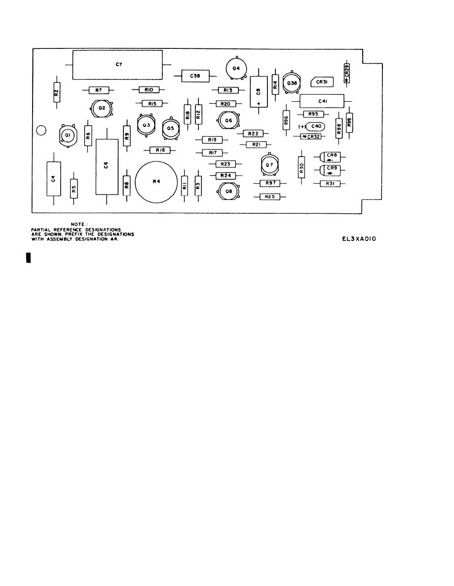
Figure 5-4. Power Supply PP-3940A/G, Component Board A4, Parts Location Diagram.
wise. Indicator should be 0 volt 0.1.
wire turns further until meter indicates zero.
(3) Lock potentiometer A3R50 with Gyptol.
5-9.
Overcurrent
Protection
Network
d. Set CUR ADJ coarse and fine control potentiom-
Adjustment
eters R53A and R53B maximum clockwise, and adjust
load to between 4.15 and 4.25 amperes. CUR MODE
Perform the following whenever transistor A4Q38 is
replaced:
indicator DS3 should not light.
a. Set power supply POWER switch S1 to off and
e. If CUR MODE indicator DS3 lights, rotate
VOLT ADJ coarse and fine controls fully counterclock-
potentiometer R54 until VOLT MODE indicator lights
and CUR MODE indicator extinguishes.
wise.
f. Readjust potentiometer R54 until CUR MODE
b. Connect load set at 5 ohms across terminals 4 and
indicator lights and current drops slightly (but re-
5 on terminal board at rear of power supply.
mains within the 4.15- to 4.25-ampere range).
c. Unsolder resistor A4R99 and remove transistor
g. Lock with Gyptol.
A3Q16 from its snap out socket.
d. Insert ZM-16/U in place of resistor A4R99 with
5-8. Voltage Programing Adjustment
an initial setting of approximately 100 ohms.
e. Set power supply POWER switch S1 to ON.
a. Set POWER switch S1 to off and remove load and
f. Slowly turn VOLT ADJ coarse and fine controls
b. Remove link between terminal board terminals 1
until the output current rises to 135 percent of the
and 2 and insert Resistor, Decode ZM-16/U between
nominal value (5.4 amperes).
terminals 1 and 3 (voltage programing), adjusting
g. Adjust ZM-16/U until the power supply shuts
ZM-16/U for exactly 4,000 ohms.
off.
h. Set power supply POWER switch S1 to off. Insert
c. Set POWER switch S1 to ON and adjust potenti-
ometer R69 to give an output voltage of 40 volts dc
the nearest standard resistor value for the ZM-16/U
&0.20, This calibrates the voltage programing to 100
resistance reading (22 to 100 ohms).
ohms/volt.
i. Perform e and f above. Power supply should turn
off when the current reaches 130 to 140 percent of
d. Turn the power off, remove ZM-16/U, and re-
nominal value (5.2 to 5.6 amperes).
place link between terminals 1 and 2.
e. Lack potentiometer R69 with Gyptol.
j. Set power supply POWER switch S1 to off. Re-
move load and reinstall A3Q16.
f. Apply input power and set VOLT ADJ coarse and
fine control potentiometers maximum counterclock-
54
Change 1

