TM 11-6125-261-30
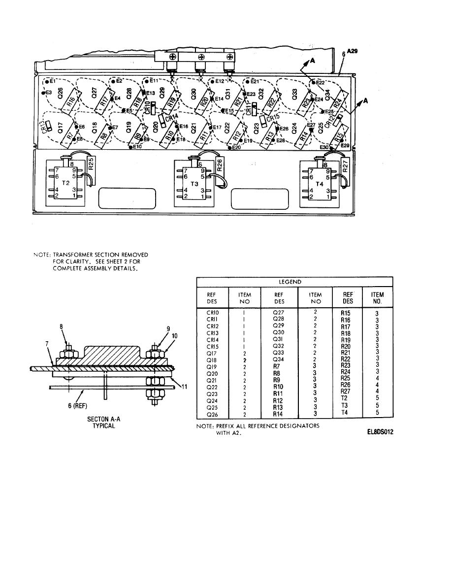
Legend for Figure 3-5.
1. Diode
13. Screw, self lock, 4-40x F
24. Washer, lock, no. 4
14. Chassis assy, left
25. Regulator assy
Transistor
2.
26. Frame, left
15. Circuit card assy
3. Resistor
27. Inductor power fltr
4. Resistor
16. Circuit card assy
28. Frame, right
17. Pulser filter assy
5. Transformer
6. Printed ckt board
18. Capacitor assy
29. Screw, mach, 6-32 x G
19. Capacitor assy
30. Screw, self lock, 6-32 x G
7. Insulator
20. Retainer brkt
31. Transformer
8. Screw, mach, 6-32 x 7/16
21. Retainer brkt
32. Capacitor
9. Stud
22. Retainer brkt
33. Transformer
10. Nut, hex, 6-32
11. Mount, transistor
23. Screw, mach 4-40 x F
34. Terminal strip
12. Screw, mach, 4-40 X F
35. Screw, self lock, 4-40 x 3/16
Figure 3-5 (l). lnverter Assembly A2 (Sheet 1 of 2).
3-28


