
TM 11-6130-243-12-1
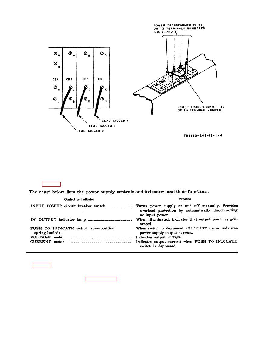
Figure 2-3. Connections on power tranformer terminals and circuit breakers for
440-volt ac input power for power Supply PP-4606A/G.
Section Il. OPERATION
2 - 4 . Controls and Indicators
b. Set the INPUT POWER circuit breaker
2-5. Operating Procedure
switch to ON and the equipment to be powered
to on.
After performing the input power con-
c. Check to see that the VOLTAGE meter
nection procedures given in paragraph 2-3, pro-
indicates between 26 and 30 volts.
ceed as described in a through d b e l o w .
d. Depress the PUSH TO INDICATE switch,
and check to see that the CURRENT mater indi-
a. Connect the dc output cable to the equip-
cates output current (200 amperes m a x i m u m ) .
ment to be powered.
10
