TM
55-1730-229-34
AG
320A0-MME-000
TO
35C2-3-473-2
TM
1730-34/1
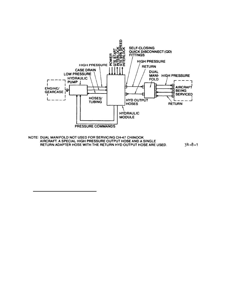
F i g u r e 8-1.
Hydraulic System, Simplified
vicing aircraft using aircraft reser-
(high pressure) hose is 1/2-inch diam-
e t e r and the return (low pressure) hose
v o i r ) , f i g u r e FO-12 (warming fluid in
is 3/4 inch diameter.
The four (two
m o d u l e ) , figure FO-13 (warming fluid in
output and two return) adapter hoses are
h o s e s ) , and figure FO-14 (bleeding air).
five feet long.
(2)
As
shown
on
figure
FO-10,
e . Hydraulic System Function. The
h y d r a u l i c fluid from the AGPU reservoir
m o s t common hydraulic system operating
is routed through a reservoir selector
m o d e is that of supplying hydraulic pow-
v a l v e and passes four temperature sen-
The hydraulic flow
er to an aircraft.
s o r s to the hydraulic pump. The temper-
diagram for this mode is on foldout
ature sensors (TS1 through TS4 on figure
F0-10.
FO-9) are set to close at various tem-
The 70F sensor (TS1)
peratures.
NOTE
c a u s e s SYSTEM READY light DS5 to illu-
minate.
This indicates that the hydrau-
Foldouts are contained in TM 55-
l i c fluid is at the minimum temperature
1730-229-12.
Sensors TS2 and TS3
for operation.
illuminate 160F and 240F indica-
If hydraulic fluid reaches
tor lights.
(1) A schematic of the hydraulic
275F , T S 4 a c t i v a t e s t o i l l u m i n a t e H I
Activation of TS4 also in-
system electrical controls and indica-
TEMP light.
t o r s is shown on figure FO-9. Hydraulic
terrupts the circuit to the load valve
f l o w diagrams for other modes of opera-
p i l o t s o l e n o i d , and shuts down hydraulic
tion are shown on figures FO-11 (ser-
power to aircraft.
8-2


