TM
55-1730-229-34
AG
320A0-MME-000
TO
35C2-3-473-2
TM
1730-34/1
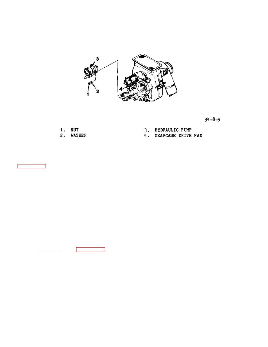
F i g u r e 8-5.
Hydraulic Pump Removal/Installation
( 6 ) Di s c o n n e c t h y d r a u l i c t u b e (1 9 ,
u p when elbow is within one turn of be-
f i g u r e 8-2) connector from elbow (9) o n
ing tight.
back of OUTPUT PRESSURE gauge (8). Re-
m o v e and discard copper seal (21).
( 4 ) Tighten elbow (9) with jam nut
(10).
(7) Remove bolts (6), nuts (7) and
standoffs (20).
(5) Insert gauge into hole in hy-
draulic control panel and secure with
( 8 ) Remove gauge (8).
bolts (6), nuts (7) and standoffs (20).
(6) Install a new 7C-4 copper seal
(9) Match mark elbow's (9) posi-
on elbow (9).
t i o n on back of gauge (8).
( 1 0 ) Loosen jam nut (10) and remove
(7) Fasten hydraulic tube connec-
e l b o w (9) from back of pressure gauge.
tor (19) to elbow (9).
Torque to be-
Remove jam nut (10).
tween 135 and 150 inch-pounds.
Install.
( S e e figure 8-2.)
b.
(8) Reinstall vent dryer as de-
s c r i b e d in paragraph 4-92, TM 55-1730-
229-12.
(1) Apply hydraulic fluid (MIL-H-
5606 or MIL-H-83282) to both sets of
t h r e a d s of elbow (9).
8-6. SIGHT GLASSES.
NOTE
(2) Install jam nut (10) on fit-
t i n g on back of gauge (8).
T h i s procedure does not require
(3) Screw elbow (9) onto gauge
that the module be removed from
Ensure that match marks are lined
(8).
the unit.
8-8


