TM 55-1730-229-34
AG 320A0-MME-000
TO 35 C2-3-473-2
TM 1730-34/1
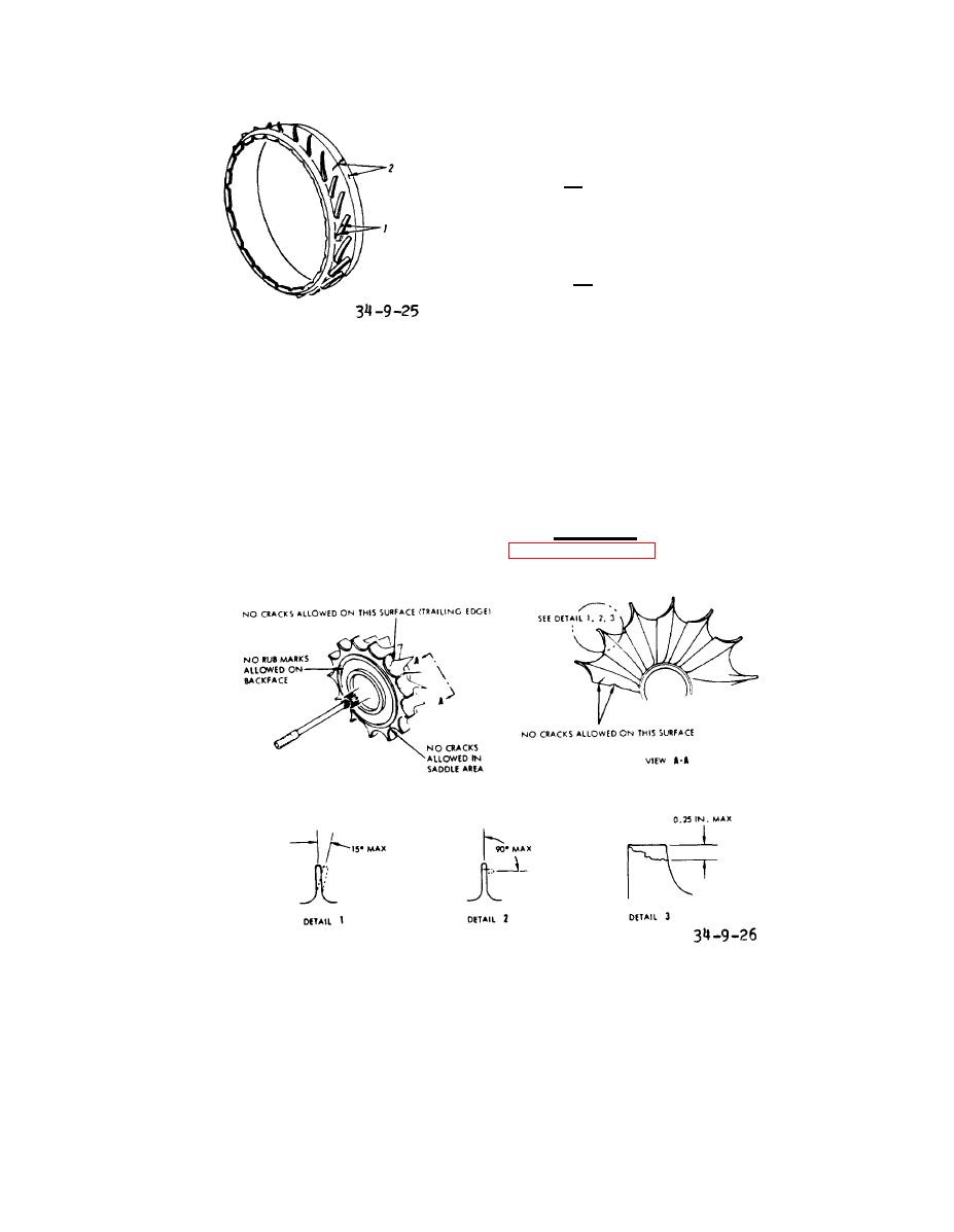
(See
ceed a maximum bend of 15 degrees.
Detail 1.)
2. Blade tips that are bent
because of erosion shall not exceed a
maximum bend of 90 degrees. (See Detail
2.)
3. Blade tips with pieces
missing because of erosion shall not ex-
ceed 0.25 inch maximum depth each blade.
(See Detail 3.)
Figure 9-25. Inspection of
(d) Visually check for rub marks
Deflector
on backface of turbine rotor. No damage
allowed.
turbine
inspect
(b) Visually
rotor blade ends, blade contour and hub
area for cracks. No cracks allowed.
(e) Visually check for cracks in
saddle area between blades. No cracks
are allowed.
(c) Visually inspect blade tips
for damage.
c. Assembly. Perform procedures
Blades that are bent due
1.
in paragraphs 9-11 through 9-15.
to foreign object damage shall not ex-
Inspection of Turbine Rotor
Figure 9-26.
9-46


