
TM 55-1730-229-34
AG 320A0-MME-000
TO 35 C2-3-473-2
TM 1730-34/1
the rear axle pinion gear via a geared
control signals to the traction motor
sleeve.
The clutch assembly is oper-
field windings.
The control signals
ator controlled by an engagement lever
from the speed/direction control assem-
mounted directly to the clutch hous-
bly consist of forward or reverse relay
A clutch q ounted microswitch
ing.
activation signals from internal micro
activates an indicator light mounted
switches and variable speed control sig-
on the speed/direction control assem-
nals from the internal variable resis-
bly. The light indicates the status of
tors. Both sets of signals are selected
the clutch lever engagement. An exter-
by the twist grips.
nal adjustment turnbuckle is provided
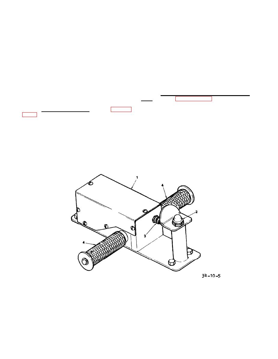
g. Speed/Direction Control Assem-
on the clutch housing to allow engaged/
(See figure 10-5) The speed/
disengaged adjustments.
bly.
direction control assembly provides both
f. Motor Controller. (See figure
the direction (forward and reverse) and
the speed commands to the AGPU propul-
forward and reverse relays are mounted
sion motor. The assembly q ounts on the
on the upper tray in the electrical com-
tow bar, close to the lunette eye. It
partment. The motor controller receives
is connected to the motor by a wiring
+28 vdc from the control panel and con-
harness that runs under the tow bar and
trol signals from the speed/direction
is protected by the tow bar channel.
control unit. It sends dc drive voltage
Forward and reverse selection as well as
to the traction motor armature and speed
speed are determined by the position of
SPEED/DIRECTION CONTROL
DO NOT TOW INDICATOR
1.
3.
ASSEMBLY
LIGHT
2.
DEADMAN SWITCH
4.
TWIST GRIP
Figure 10-5.
Tow Bar Controls
10-6
