
TM 11-6130-266-15
and then connect the ac power cord to a 3-wire
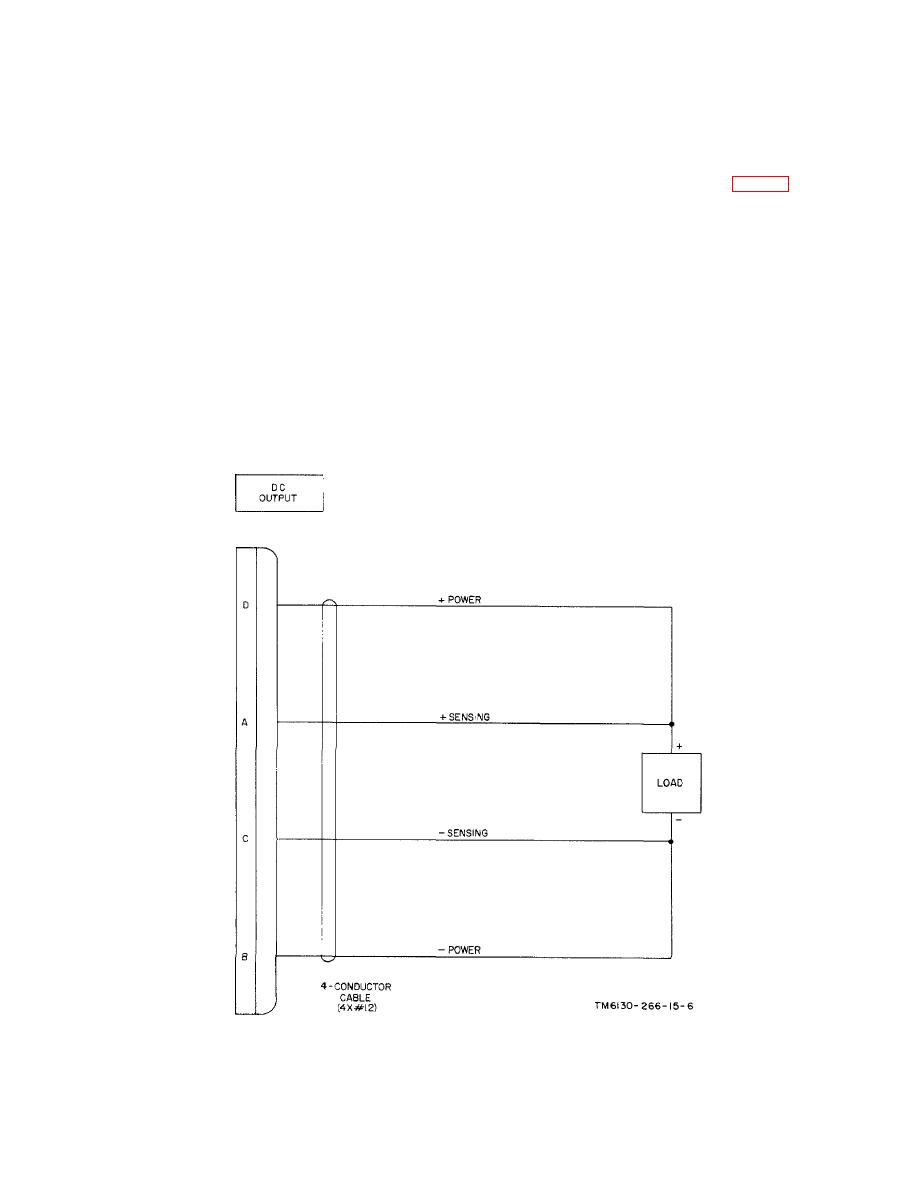
(2) Remote. Use a 4-conductor cable (not
grounded ac power source. (To avoid possible electrical
supplied) to connect the remote load terminals to DC
shock, 2-wire adapters must not be used).
OUTPUT receptacle J6 on the front panel. Connect the
load leads (power) to pins D (+) and B (-). Connect the
sensing leads to pins C (-) and A (+) (fig. 2-4).
NOTE
Loads
may
be
connected
NOTE
simultaneously
to
DC
OUTPUT
receptacle
J6
and
DC
OUT
At the load, be sure that the positive
receptacles J7 and J9 providing the
sensing lead is connected to the
total output current drain is less than
positive terminal and the negative
25 amperes.
sensing lead is connected to the
negative terminal.
d. Determine whether local or remote operation is
required. Each type of operation is described below:
e. Check to see that the standby battery is
connected to BAT IN receptacle J8 on the rear panel.
(1) Local. Use the dc power cord to connect
the load directly to DC OUT receptacle J7 or J9 on the
f. If a battery is to be charged, disconnect and
real panel (pin A (-), pin B (+) ).
remove the standby battery connected to
Figure 2-4. Power Supply PP-6224/U, remote cabling.
2-4

