
TM 11-5820-765-34
Section III.
T E C H N I C A L PRINCIPLES OF OPERATION
1-10.
BLOCK
DIAGRAM
ANALYSIS
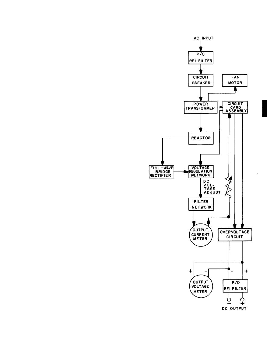
The block diagram describes the power sup-
ply's major electronic components and circuits.
The power supply requires an input of 115
volts ac or 230 volts ac for operation, and has an
output of 27-29 volts dc.
Input power: Applied through a radio frequen-
cy interference (RFI) filter to the circuit breaker.
With the circuit breaker closed (POWER ON),
input power flows to the power transformer,
which feeds the fan motor, circuit card
assembly, and all of the power supply's circuits.
Output: The transformer applies power
through a reactor to a full-wave bridge rectifier,
which converts the input flow to dc. A silicon
controlled rectifier regulates the dc output; con-
trol circuitry in the circuit card assembly pro-
vides automatic, continuous voltage regulation.
A filter network purifies the dc signal; the
regulated positive dc output flows through
the
output current meter (ammeter) and is shunt to
the dc output terminal.
A voltage adjust circuit permits manual adjust-
ment of the output voltage; controls in the cir-
cuit card assembly sense the adjustment and
change
the
voltage.
An
overvoltage
circuit,
activated
when
needed,
applies a short-circuit load to the output ter-
minals, opening the circuit breaker. This pro-
tects the power supply and the equipment being
powered.
The
output
voltage
meter
monitors
output voltage, which passes again through the
RFI filter before reaching the dc output terminal.
