
TM 11-5820-765-34
Procedure:
Set transformer for 1 15-volt output.
Remove
dc
voltage-adjust
panel
cover.
Open
front
panel.
Switch CB1: ON
Set dc voltage-adjust control R4 fully clockwise.
Loosen locknut on variable resistor R8.
Adjust R8 until power supply voltage is 29 volts minimum, 30 volts maximum,
(take reading on Voltmeter AN/URM-145).
Tighten
locknut.
CB1: OFF
Close front paneI.
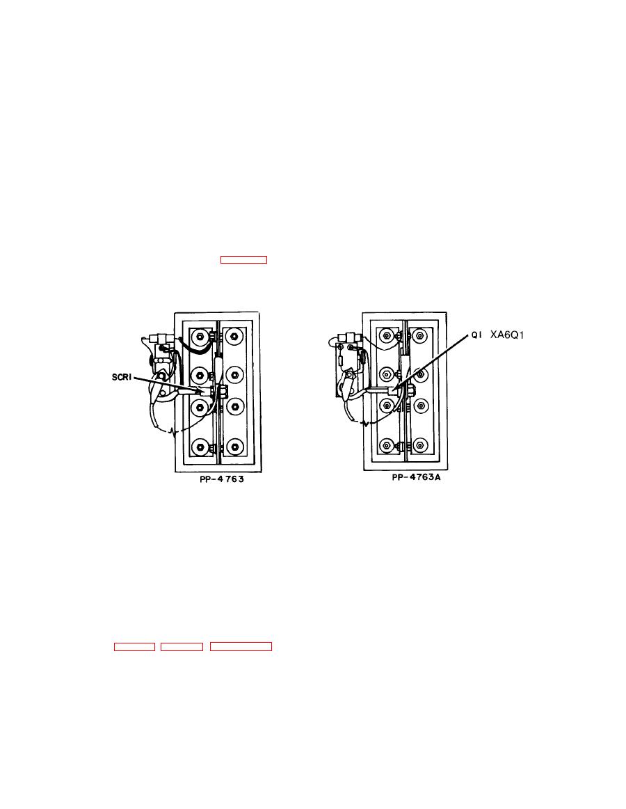
Overvoltage Circuit
Remove rear panel (refer to para 2-10).
Connect jumper lead across silicon Controlled Rectifier SCRI (Q1) as shown. Use No. 8 (or
larger) AWG wire.
Set transformer to 115-volt output.
With no load connected across power supply's dc output:
Increase AC line voltage input to power supply until dc output reads 35 volts 0.1 volt (on
Voltmeter ME-30(*)/U), or until Controlled Rectifier SCR2(Q2) fires, tripping CB1.
If SCR2(Q2) does not fire:
Turn Variable Resistor PC101R123(A1R23) clockwise until SCR2(Q2) fires at 35 volts 0.1 volt.
Refer to figure 1, figure 2, Chapter 3-6.
Seal
adjustment
screw
on
PC101R123(A1R23).
Remove all input power to supply.
Remove jumper leads from SCR1(Q1).
Replace rear panel.
2-21
