TM 11-5820-765-34
2 - 8 . VOLTAGE AND RESISTANCE DATA
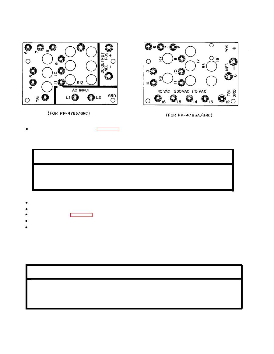
Open front, remove top panel (para 2-10). Pull interlock switch up.
VOLTAGE OUTPUT, POWER TRANSFORMER T1
Voltage measurements, T1 secondary windings, normal operating conditions:
AC voltage indication (approximate)
Between secondary
PP-4763A
PP-4763
winding terminals
52.0
50
TB4-2
TB4-1
115.0
115.0
TB1-10
TB1-11
TB1-7
32
33.4
TB1-6
TB1-8
66.7
TB1-6
64
D C RESISTANCE, TRANSFORMER and REACTORS
Measure resistance with power OFF.
Disconnect power plug, turn switch OFF before taking measurements.
Remove top panel (para 2-10).
Check transformer, reactors for defects before making resistance measurements.
Use troubleshooting chart.
CAUTION
Normal
resistance
measurements
may not detect some
arcing
and
shorting
that
occurs
during
normal operation. Use sight, smell, and hearing to try to isolate defective part.
Convert readings to zero or
DC resistances:
change test equipment
Transformer,
Resistance (ohms) (*)
Between terminals
reactors
TB1-12
0.06
T1
TB1-3
PP-4763
0.015
TB4-1
TB4-2
2.6
TB1-11
TB1-10
0.40
TB1-8
TB1-6
0.40
TB1-8
TB1-7
NOTE
(*) For all readings below 1 ohm, table should read less than 1 ohm.


