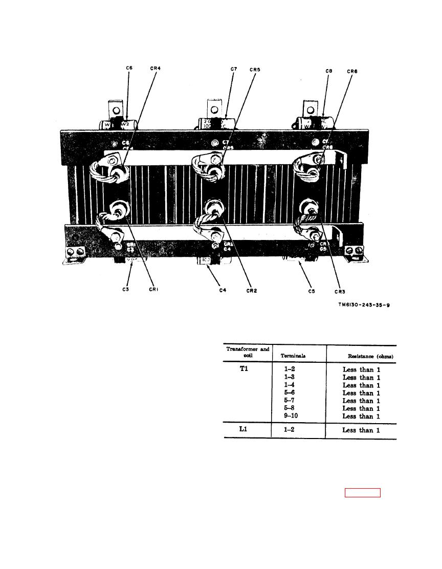
TM 11-6130-243-35
that faulty operation is probably
caused by a faulty transformer or
coil. To do this, follow the trouble-
shooting procedures in paragraph 2-
4d.
(2) Do not use the resistance measure-
ments as the sole basis for discard-
ing a transformer or coil as defective.
Resistances may vary from one trans-
former or coil to another because of
broad winding tolerances during
manufacture. The values given in
2-6 Capacitor Test
the chart ((3) below) are typical
Filter capacitors C1 and C2 are rated at
average values for all groups of
10,000 microfarads (f), 50 volts dc; capaci-
transformer windings and coils.
tors C3 through C8 are rated at 2 f, 100
volts dc. Test each capacitor (figs. 2-3 and
(3) Dc resistances of transformers and
2-4 with Analyzer ZM-3A/U. Refer to the
coils are as follows:


