TM 11-6130-266-15
Item No.
Trouble symptom
Probable cause
Corrective action
3
With AC and NORM indicator
No dc power reaching OUTPUT
a. Check resistor A6A1R2 and re-
lamps DS1 and DS2 lit, OUT-
METER Ml.
place if necessary.
PUT METER M1 fails to in-
b. Check S2 and replace if necessary.
dicate output voltage. (VOLT-
c. Check M1 and replace if necessary.
AGE CURRENT switch S2 in
VOLTAGE position and DC
circuit breaker CB2 is ON.)
Multimeter indicates normal
output voltage.
4
Same as Item No. 3, except mul-
a. DC circuit breaker CB2 defective.
a. Check CB2 and replace if neces-
timeter also
ails to indicate
sary.
output voltage.
b. Auxiliary supply and control as-
b. Check for +28 to +32V dc be-
sembly A1 defective.
tween pin 15 and pin 17 of A1.
Replace A1 if necessary.
c. Relay A6K1 defective.
c. Check A6K1 and replace if neces-
sary.
5
OUTPUT METER M1 indicates
a. Potentiometer R3 defective.
a. Check R3 and replace if necessary.
voltage but rotating DC
b. Auxiliary supply and control as-
b. Check A1 and replace if necessary.
OUTPUT ADJ potentiometer
sembly A1 defective.
R3 fails to change indication .
c. Resistor A6A1R3 defective.
e. Check A6A1R3 and replace if
necessary.
d. Post regulator control assembly
d. Check A2 and replace if neces-
A2 defective.
sary.
TM 6130-266-15-C1-4
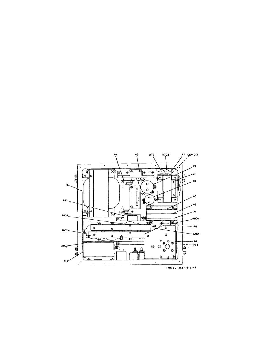
Figure 5-1. Power Supply PP-6224/U, top view, parts location.
Change 3 5-3


