
TM 11-6130-266-15
TM 6130-266-15-9
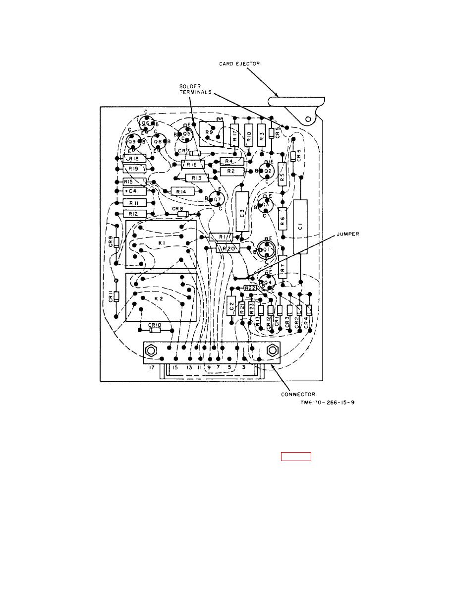
Figure 5-2. Board Assembly A1, parts location.
determine whether faulty operation is due to one of
5-7.
Resistance of Transformers, Inductors, and
these parts. To do this, follows the troubleshooting
procedures (para 5-5d) and make the voltage checks
given in the voltage and resistance chart.
CAUTION
Make resistance measurements with
(2) Do not use the resistance measurements
input power off.
as the sole basis for discarding any of these parts as
a. The resistance values are provided as an aid to
defective. Because of broad winding tolerances during
troubleshooting. When using the data, observe the
manufacture, resistances of identical coils may vary from
following instructions:
the chart values, which are typical average values.
(1) Before making resistance measurements,
Change 3 5-5
