TM 11-6130-266-15
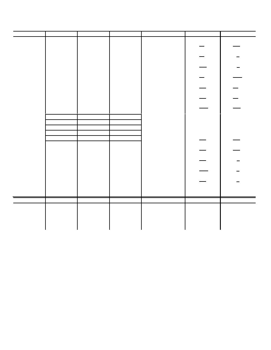
Ref des
VE
VB
VC
Voltage ref pt
RRE
RBC
A1Q8
+12.0
+11.2
+3.0
Pin 17
1K
950
2K
10K
A1Q9
+2.2
+3.0
+2.6
Pin 17
4K
∞
880
800
A2Q1
+1.0
+1.70
+10.0
Pin 8
30K
∞
900
825
A2Q2
-0.1
-0.7
-19.0
Pin 3
1K
1.1K
4K
∞
a
A2Q3A
+8.8
+9.1
+13.0
Pin 2
800
9K
1.1K
1K
a
A2Q3B
+8.5
+9.1
+15.0
Pin 2
800
7K
1.1K
950
A2Q4
0.0
0.0
+16.0
Pin 2
1.1K
10K
800
800
b
A2A1
V2
V3
V4
Pin 2
0.0
0.0
-16.0
Pin 2
--
--
V5
V6
V1
Pin 2
--
--
-15.0
-5.2
+16.0
Pin 2
--
--
e
A3Q5
0.0
0.0
32.5
A8C2 (-)
100
200
100
200 (d)
e
A3Q6
0.0
0.0
32.5
A8C2 (-)
100
200
100
200 (d)
A5Q1
0.0
0.0
+15.5
Pin 14
950
∞
800
800
A5Q2
0.0
0.0
+15.5
Pin 14
3.8K
∞
900
800
A5Q3
0.0
-0.05
+32.5
Pin 8
400
∞
400
800
SCR's only
Gate
Cath
Anode
Voltage ref pt
RGK
RAK
A4Q1
-0.25
0.0
-32.5
A4A2P1-10
100-1K
∞
100-1K
∞
A4Q2
-0.25
0.0
-32.5
A4A2P1-10
100-1K
∞
100-1K
∞
a A2Q3A and, A2Q3B are in 1 case
b Resistance data not valid
c RBE and RBC measurements made with A3 in circuit
d Voltage is average of square wave
e SCR voltages are waveform averages
isolating transformer between the iron the line. Use a
5-9. General Parts Replacement Techniques
All the parts of the power supply can be replaced without
higher wattage soldering iron for heavier duty soldering.
special procedures. The following precautions apply
specifically to this equipment.
CAUTION
a. Do not disturb the setting of any potentiometer.
Do not use a soldering gun;
b. The power supply is transistorized. Use a
damaging voltage can be induced
pencil-type soldering iron with a 25-watt maxi mum
into components.
capacity. If the iron must be used with ac use an
5-8.2 Change 3


