TM 5-1730-245-14
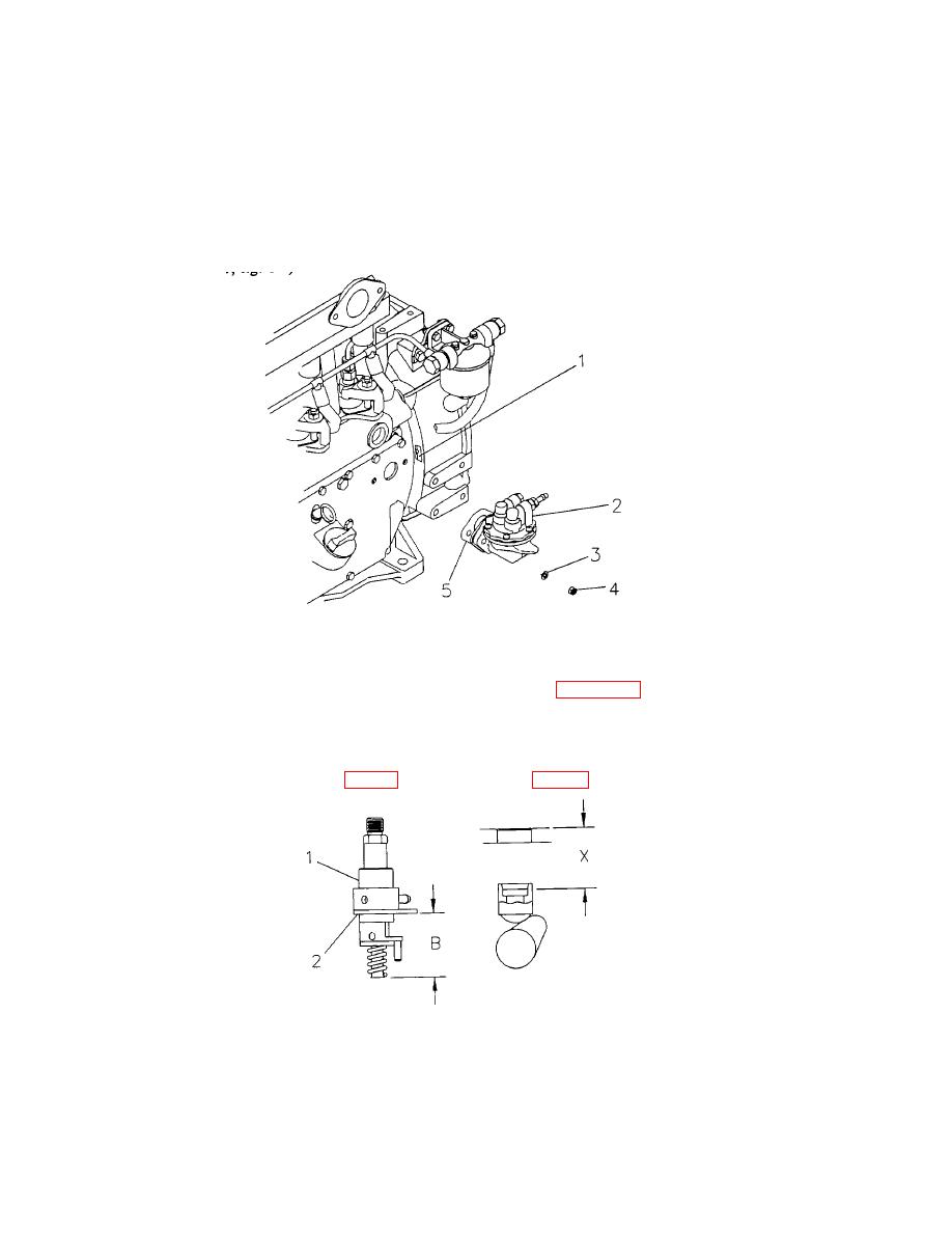
1) Remove the nut (4), flatwasher (3) fuel lift pump (2) and gasket (5) to provide access to the flywheel
timing window (1) in the crankcase.
2) The compression stroke can be determined by feeling the fuel pump tappet which will be rising to
cause injection. Both valves will be closed. If the engine has been rotated past the 20 degree mark in
the direction of rotation, turn it back past the mark and bring it up again in the direction of rotation in order
to eliminate any gear backlash.
3) Set the related piston at 20 degrees before Top Dead Center (TDC) on the compression stroke by
rotating crankshaft pulley (5, fig. 67) clockwise.
Figure 6-9. Flywheel Timing Window.
3) Using a depth micrometer, measure the distance between the top face of the crankcase to the top of
the fuel pump tappet cap. This is shown as dimension "X" in figure 6-10 below.
4) Subtract this dimension from dimension "B" (2.012 in./51.2 mm). This gives the required thickness of
shims to be inserted between the fuel pump plate (2) and the crankcase.
5) Install the fuel lift pump (2, fig 6-9) and new gasket (5, fig. 6-9).
Figure 6-10. Fuel Pump.
6-11/(6-12 blank)


