
TM 55-1730-229-12
AG 320A0-OMM-000
TO 35C2-3-473-1
TM 1730-12/1
12-4-12(3)
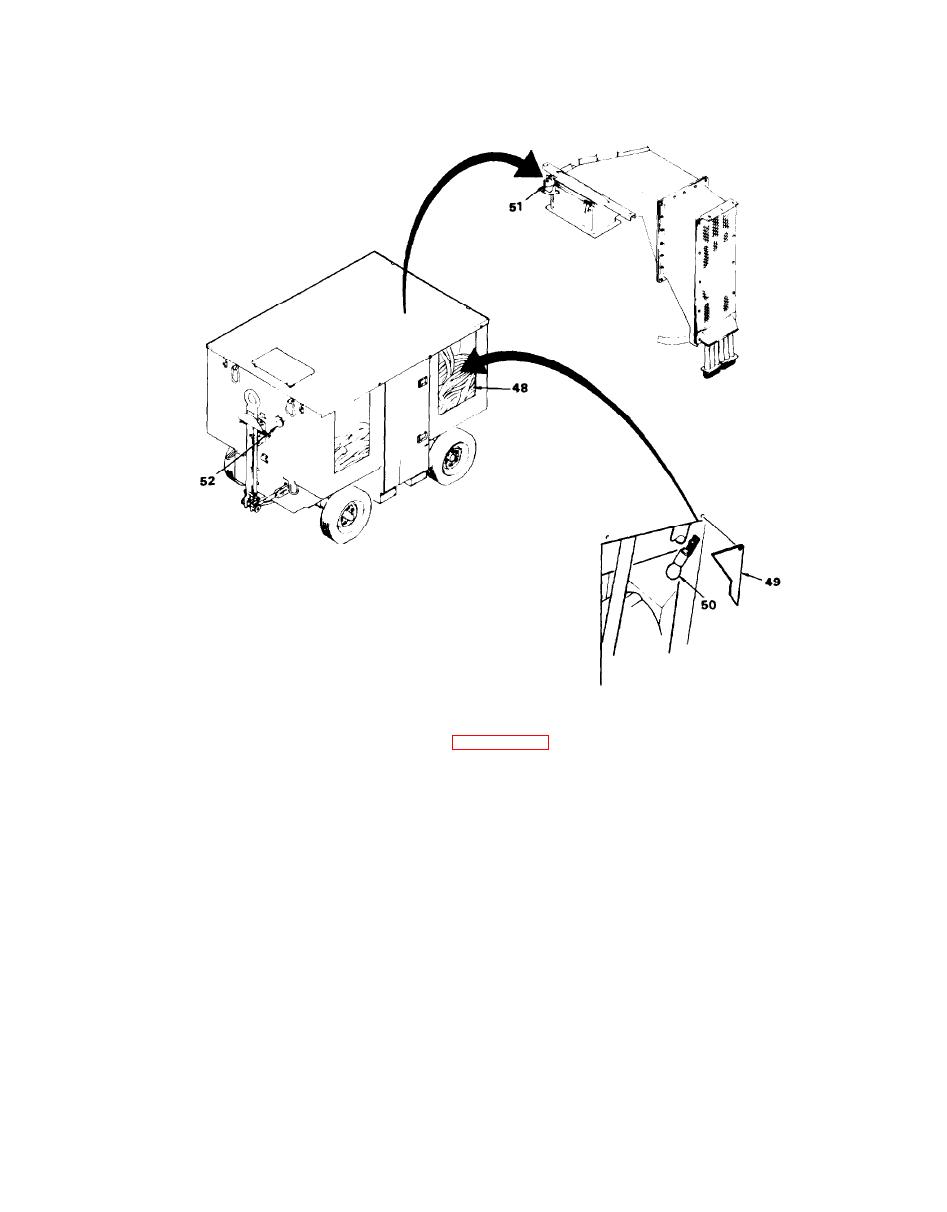
NOTE: See table 4-10 for legend.
Figure 4-12. DC Electrical and Control System Components (sheet 3 of 3)
unit designators. AGPU unit designators
(1) Electrical components are
include unit 1 (control panel), unit 2
identified on schematics and wiring
(upper electrical tray), and unit 3
diagrams by reference designators. Ref-
Throughout
erence designators include one or two
(lower electrical tray).
these procedures, reference designators
letters followed by one or more numbers,
such as K1. The letter K identifies the
are preceded by the unit designator
For example K1 iden-
where applicable.
component type (relay), and the number 1
identifies a specific relay. Some elec-
tifies a relay mounted on the AGPU main-
frame (electrical bulkhead in this in-
trical components are mounted directly
to the AGPU mainframe, while others are
stance), and 3K1 identifies a relay
mounted on the lower electrical tray.
mounted on removable assemblies with
