
TM
55-1730-229-12
AG
320A0-OMM-000
TO
35C2-3-473-1
TM
1730-12/1
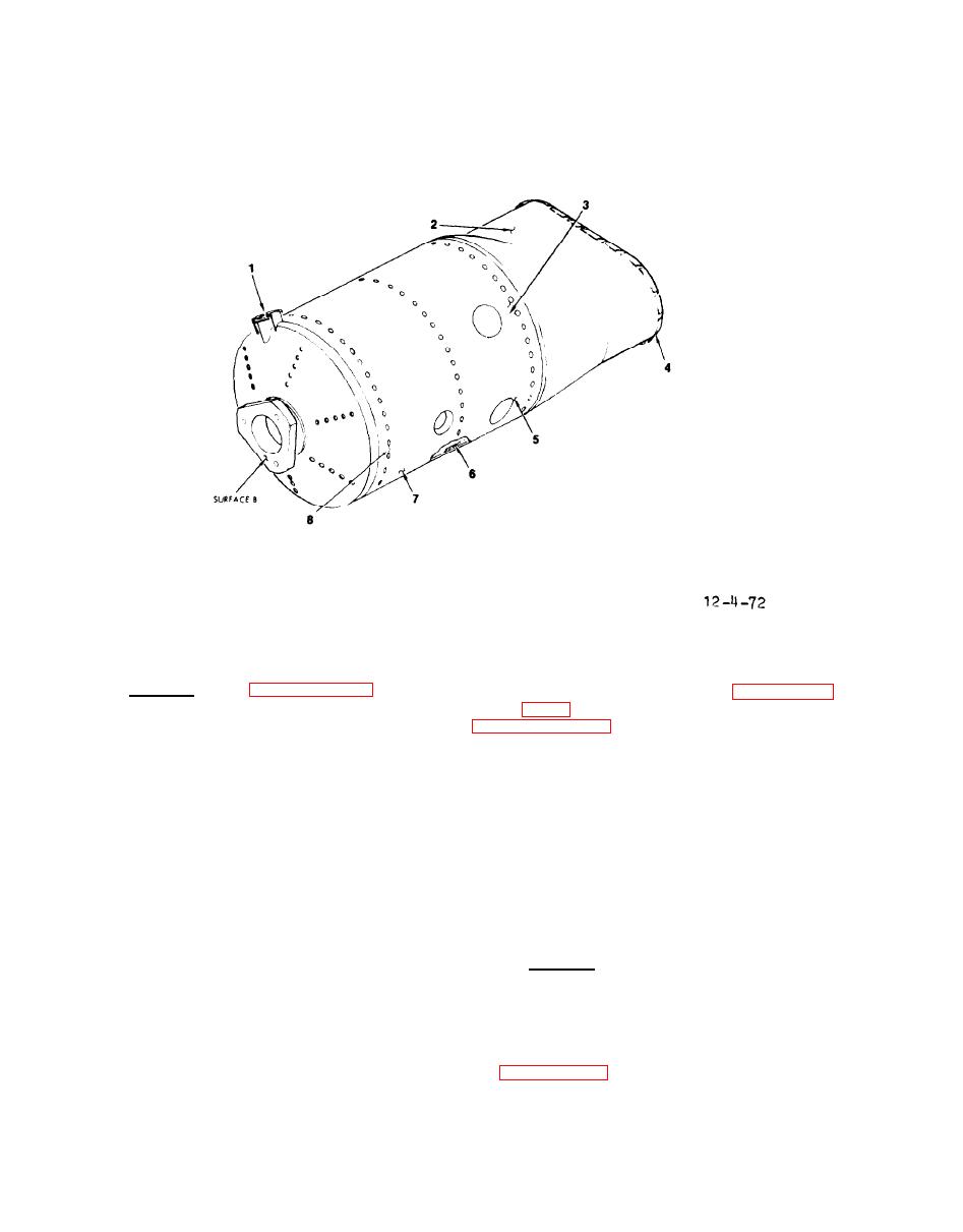
Combustion Chamber Inspection/Check
c.
Install.
(See figure 4-71.)
(5) Install igniter plug (para-
graph 4-81) and combustor check valve
(1) Apply a thin coat of high tem-
perature
compound MIL-A-907 (Fel-Pro
(6) Reconnect fuel line (1) to
C5-A) to threads of bolts (4).
fuel nozzle (5).
ENGINE WIRING HARNESS.
(2) Place combustion chamber cap
(7) over combustion chamber (8), align-
ing igniter plug boss of combustion
NOTE
chamber cap (7) with igniter plug hole
in combustion chamber (8).
The engine wiring harness connects
between the ECU (P2) and all engine-
(3) Install gasket (6), fuel noz-
mounted components.
zle (51, and bolts (4) to combustion
chamber cap (7).
Tighten bolts to a
a.
Inspect.
torque value of 50 inch-pounds.
Lock-
wire bolts.
(1) Set MASTER SWITCH to OFF.
(4) Install assembled items (4
(2) Inspect wiring harness for
through 8) into engine, and tighten
damaged insulation and broken wires.
clamp (2) to a torque value of 45 inch-
See figure FO-3 for wiring identifica-
pounds.
tion and connections.
