
TM
55-1730-229-12
AG
320A0-OMM-000
TO
35C2-3-473-1
TM
1730-12/1
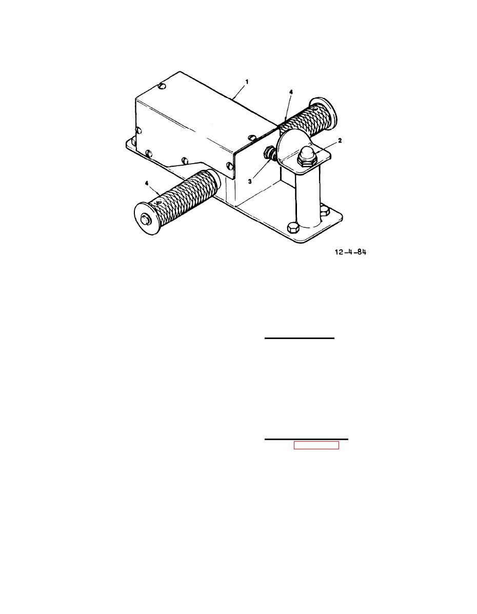
SPEED/DIRECTION CONTROL
1.
DO NOT TOW INDICATOR
3.
ASSEMBLY
LIGHT
2.
DEAD MAN SWITCH
4.
TWIST GRIP
Tow Bar Controls
of the control twist grips (5).
The
c. Brake Assembly. The AGPU uses
twist grips can be actuated from either
rear-wheel brakes that are controlled by
side of the tow bar.
The twist grips
an operator-activated mechanical lever
are spring loaded to a neutral, no-
connected to the brakes on a cable. The
propulsion position.
The twist grips
brakes are standard,
automotive-type
rotate in either direction, one way con-
drum units using replaceable brake
trolling forward direction and speed,
shoes.
and the other way reverse direction and
speed.
The controller contains an
FRONT AXLE ADJUSTMENTS.
emergency dead man switch that must be
depressed to operate the speed/direction
controls.
Release of the switch dis-
a. Toe-In Adjustment. If original
connects all power to the traction
tie-rod (21, figure 4-83) length is un-
motor.
A mercury switch is in the
known, it will be necessary to perform
same line as the dead man switch. The
toe-in adjustment.
To adjust toe-in,
mercury switch opens the power system
the AGPU should be sitting on a level
supply when the tow bar is raised to
surface.
The tires should be properly
approximately 60 degrees or more from
inflated.
Using a steel tape measure,
horizontal.
The assembly also incorpo-
measure and record the exact distance
rates an indicator light (4) with a
from the front center bead of the left
press-to-test feature that is illumi-
tire tread to the front center bead of
nated when the propulsion motor clutch
the right tire tread.
Now measure and
is engaged.
record the same measurement between the
