
TM 55-1730-229-12
AG 320A0-OMM-000
TO 35C2-3-473-1
TM 1730-12/1
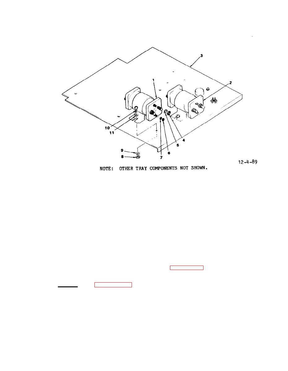
1.
RELAY K-1
7.
WASHER, LOCK
2.
RELAY K-2
8.
NUT
3.
UPPER TRAY
9.
WASHER, LOCK
4.
NUT
10.
SCREW
5.
WASHER, LOCK
11.
WASHER, FLAT
6.
NUT
Control Relays K1 and K2
holes in upper tray (3). Install lock-
(8) Tag and remove wires from rear
washers (9) and nuts (8) on screw (10).
of K-1 and K-2 control relays (1 and 2).
(9) Remove nuts (8), lockwashers
(3) Connect external wires to rear
(9), screws (10), and flat washers (11),
of K-1 (1) and K-2 (2) control relays.
securing K-1 and K-2 control relays (1
See figure 4-90 for proper connections.
and 2) from electrical compartment upper
tray (3).
(4) Install lockwashers (5) and
b.
Install.
(See figure 4-89.)
nuts (4).
(1) Position K-l and K-2 control
(5) Connect external wires to
relays (1 and 2) on upper tray (3). En-
sure relays are properly positioned
front of K-1 and K-2 control relays (1
and 2).
(front and rear).
(6) Install lockwashers (5 and 7),
(2) Install flat washers (11) on
nuts (4 and 6).
screws (10) and install screws through
