TM 55-1730-229-34
TO 35C2-3-473-2
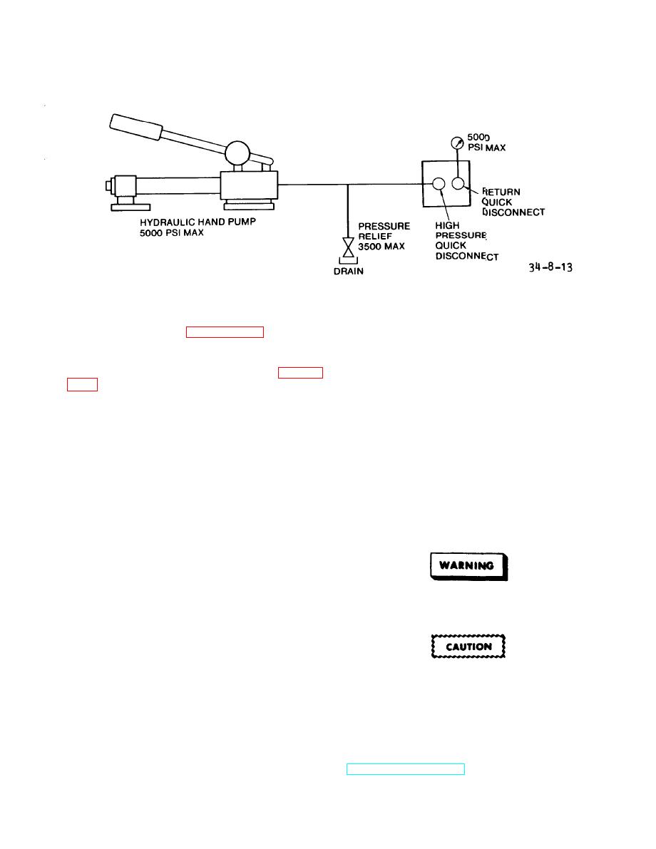
Figure 8-13.
Dual Manifold Test Set-Up
(See figure 8-13.)
return path. Valves and fluid
Test.
d.
ports are provided for filling and
draining hoses.
(1) Connect hydraulic dual mani-
fold to test set-up as shown in figure
(2) Pressurize dual manifold with
hand pump to 3,300 psi and let set for
1/2 hour with no change on gauge. Look
NOTE
for external leaks. If no leaks, remove
The single input is branched to
drain port cap. Open drain/fill valve.
Release pressure and disconnect test
two equal output lines and two re-
turns are combined into a single
set-up.
Section III.
MODULE DISASSEMBLY
8-16.
DISASSEMBLY.
8-15. INTRODUCTION. This
section
contains the procedure for total disas-
sembly of the hydraulic module. To gain
access to, remove, and re-install cer-
Insure Hydraulic System is not
tain components the module must be to-
under pressure before starting
With some small
tally disassembled.
work on Hydraulic System.
variations, there is essentially only
one possible sequence for disassembly
(and re-assembly) of the module. If the
prescribed sequence is not followed it
will be difficult, if not impossible, to
Always put plastic plugs into con-
nectors and plastic caps over fit-
gain access to and torque hydraulic fit-
tings upon disconnection. This
tings during re-assembly.
protects threads and prevents con-
tamination.
a. Drain fluid from hydraulic module
as described in paragraph 3-9.d. of
TM 55-1730-229-12.
Change 5
8-25


