
TM 55-1730-229-34
AG 320A0-MME-000
TO 35 C2-3-473-2
TM 1730-34/1
Install.
f.
(See figure 10-6.)
(10) Install tow bar in accordance
with paragraph 4-113, TM 55-1730-229-12.
(1) Position axle beam (5) under
AGPU body with floor jack.
(11) Install speed/direction con-
trol assembly in accordance with para-
(2) Raise axle beam (5) within two
graph 4-118, TM 55-1730-229-12.
inches (2") of spring (8). Support axle
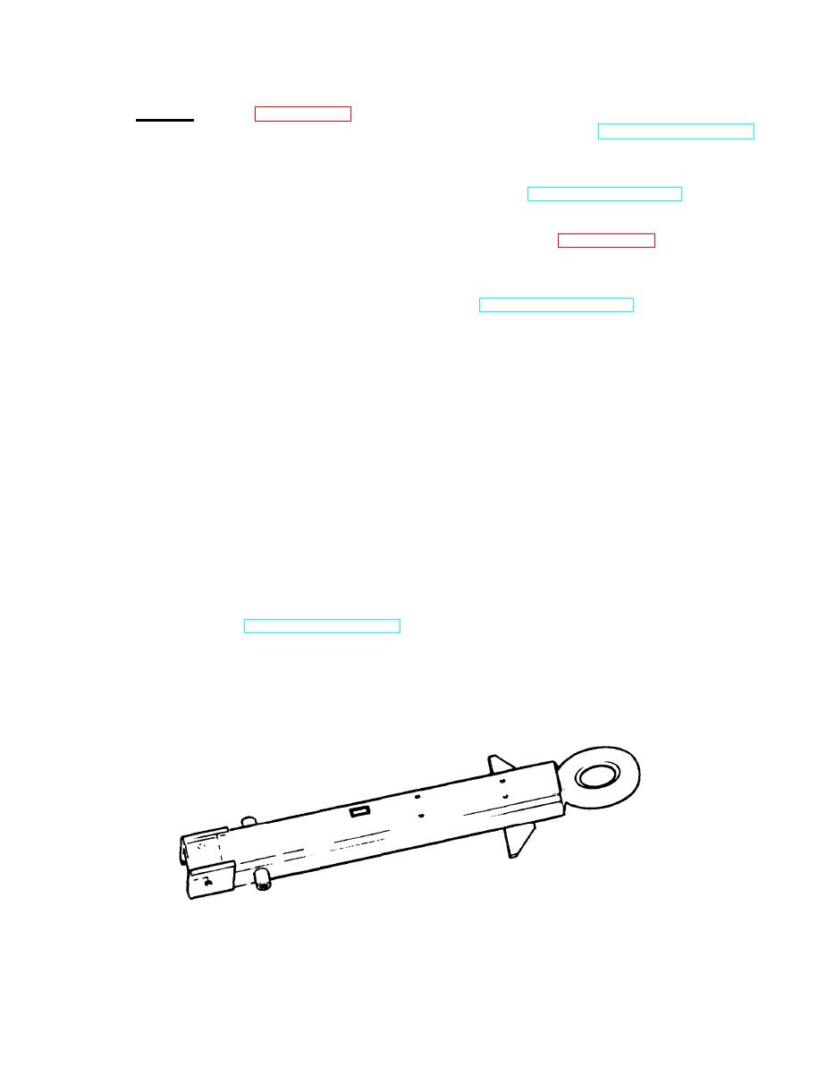
10-3. TOW BAR ASSEMBLY. Inspect and
beam (5) with two jack stands, leaving
floor jack in position.
repair tow bar, figure 10-9, as follows:
(1) Remove speed/direction control
(3) Install alignment pin (9) into
alignment hole (7) on axle beam (5).
assembly in accordance with paragraph
4-118, TM 55-1730-229-12.
(4) Position spacer (6) on axle
beam (5) so that center hole in spacer
(2) Remove tow bar assembly in ac-
is aligned with pin (9).
cordance with paragraph 4-113, TM 55-
1730-229-12.
(5) Raise axle beam (5) with floor
jack until alignment pin on bottom of
(3) Tow Bar Beam. Check the beam
spring (8) engages spacer's (6) align-
for physical damage.
Dents, bends or
twists may be repaired using a hydraulic
ment hole.
arbor press or heavy clamps and hammers.
(6) Position upper plate (3) on
Inspect lunette eye for proper alignment
Minor lunette eye
top of spring (8).
and secure welds.
misalignment may be corrected by placing
(7) Install U-bolts (4) around
the tow bar beam In a heavy vice and
axle beam (5) and through holes in upper
twisting the eye with a large bar in-
plate (3). Install lockwashers (2) and
serted through the eye. Major misalign-
nuts (1) on U-bolts (4). Torque U-bolts
q ent may require heating of the entire
to 60 foot-pounds.
lunette eye. Reweld the tube joints if
Inspect the tow bar pivot
necessary.
(8) Install wheels in accordance
bolt alignment. Correct by bending the
Excessive
with paragraph 4-112, TM 55-1730-229-12.
beam in a hydraulic press.
wear of the pivot bolt mounting holes
(9) Raise AGPU, remove jack
requires replacement of the tow bar
stands, lower AGPU.
beam.
34-10-9
Figure 10-9.
Tow Bar Beam
10-13
