TM 11-6130 -243-14-3
refinishing practices specified in TB 430118. Refer
d. Clean the front panel, meters, and control
to SB 11573 for supplies available for field painting
knobs; use a soft cloth. If necessary, dampen the cloth
and preservation.
with water; mild soap may be used for more effective
cleaning.
39. General Troubleshooting Information
3-8. Touchup Painting Instructions
Troubleshooting the power supply is based upon the
operational check contained in the preventive
NOTE
maintenance checks and services daily schedule (para
Touchup painting recommended instead of
refinishing whenever practical;
all functions starting with Item #5 in the preventive
screwheads, binding posts, receptacles,
maintenance checks and services daily schedule (para
and other plated parts will not be painted
or polished with abrasives.
mal indication or result is observed; note the item
number in the troubleshooting chart (para 3 11). If
Remove rust and corrosion from metal surfaces by
the corrective measures indicated do not result in cor-
lightly sanding them with fine sandpaper. Brush two
rection of the trouble, higher category maintenance is
thin coats of paint on the bare metal to protect it from
required.
further corrosion. Refer to applicable cleaning and
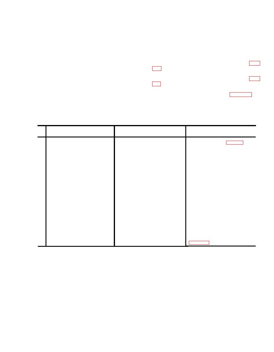
3-10. Troubleshooting Chart
Item
Checks and Corrective
Trouble Symptom
Probable Cause
No.
Measures
1
PILOT LIGHT does not light
Defective PILOT LIGHT
Replace indicator lamp (para 3 11 )
a. VOLTS meter indication does not
a. VOLTS meter is defective or OUTPUT
2
a. Higher category maintenance is re-
vary in accordance with changed
VOLTAGE ADJUST switch is shorted.
quired.
settings of OUTPUT VOLTAGE
ADJUST switch.
b. AMPS meter indicates zero at all
b. AMPS meter is defective or AM-
b. Higher category maintenance is re-
quired.
times.
METER SWITCH is open.
3
With CIRCUIT BREAKER switch set
Short circuit across CIRCUIT BREAKER
Higher category maintenance is required.
to OFF, VOLTS meter or AMPS meter
switch.
does not indicate zero, and PILOT
LIGHT does not extinguish.
Inspect cable insulation. With power dis-
4
Cable insulation cuts, burns, abrasions,
Defective cable or cables.
connected and CIRCUIT BREAKER
or pinch marks that could cause short
switch ON, check continuity between any
circuits or open circuits.
two input power leads with Multimeter
than 5 ohms. Check continuity between
ground lead on input cable and cart
chassis with multimeter. Resistance
should be less than 5 ohms. Check con-
tinuity between two output leads with
multimeter. Resistance should be less
than 5 ohms. If necessary, replace cables
(paras 3-12 and 3-13.)
b. Loosen the input cable strain relief by rotating
3-11. Replacement of Indicator Lamp
the outer cover counterclockwise.
a. Turn t h e glass i n d i c a t o r lamp jewel
c. Remove the four screws attaching the input
counterclockwise and pull it out to expose the defec-
cable to the input filter.
tive lamp.
d. Remove the input cable.
b. Press in on the indicator lamp and turn it
e. Replace the cable.
counterclockwise to unlock it.
f. Reassemble the power supply by reversing steps
c. Pull the defective indicator lamp out and replace
c through a above.
it with a new one. Push the indicator lamp in and
twist clockwise to lock it,
3-13. Replacement of Output Cables
a. Remove top cover from power supply by
3-12. Replacement of Input Cable
removing the four cover screws.
a. Remove top cover from power supply by
b. Loosen the two output cable strain reliefs by
removing the four cover screws.
rotating the outer covers counterclockwise.
3-3


