
TM
55-1730-229-12
AG
320A0-OMM-000
TO
35C2-3-473-1
TM
1730-12/1
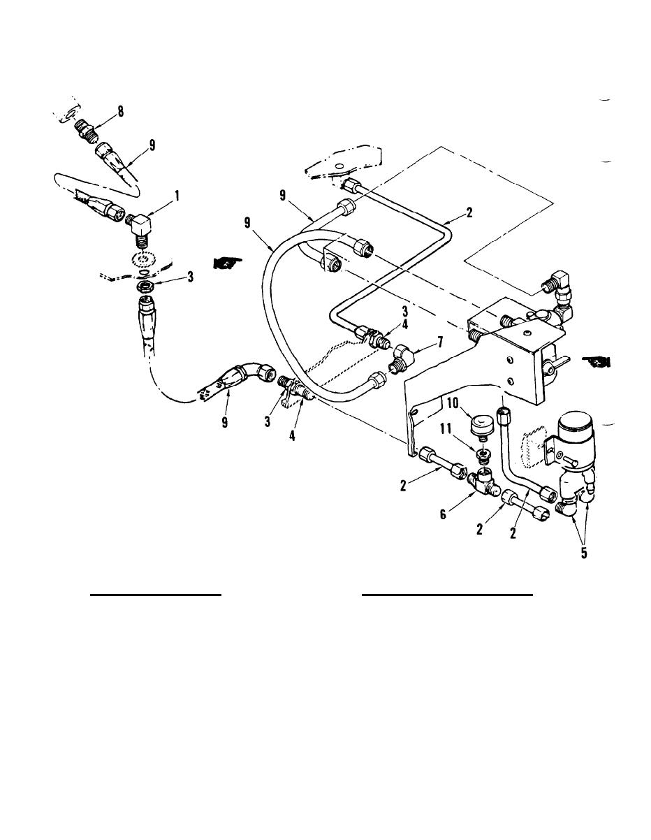
1.
FITTING, FUEL TANK 7.
ELBOW, M/F
(BOTTOM)
8.
UNION, M/M
2.
TUBE ASSEMBLY
9.
HOSE ASSEMBLY
3.
NUT
10.
SENSOR, PRESSURE
4.
UNION, BULKHEAD
11.
FITTING
5.
ELBOW
12.
FCU
6.
TEE
b. Scavenge Bleed Air. A small
c. Load Control Valve (LCV). The
amount of bleed air is continually used
LCV is controlled by the electronic con-
The ECU receives a
by the air cleaner (5) when the engine
trol unit (ECU).
is running. Bleed air is routed to six
signal to open the LCV when the PNEU-
nozzles (6) on the bottom of the air
MATIC POWER switch on the control panel
cleaner. Air flowing through these noz-
is set to ON position. The LCV consists
zles creates a partial vacuum inside the
of a housing containing a filter (15), a
air cleaner housing.
This pulls dirt
control pressure regulator (14), a re-
separated by the centrifugal air cleaner
strictor, a rate control orifice, a
tubes (8) out of the housing, and expels
torque motor (12), and a pneumatic actu-
the dirt out scavenge tubes (9) on the
Compressor bleed air enters
ator (16).
bottom air cleaner.
through a passage in the valve housing
Change 2
