
TM 55-1730-229-12
AG 320A0-OMM-000
TO 35C2-3-473-1
TM 1730-12/1
(d) Solder all wires removed in
1S12).
step (1) to solder lugs on switch.
NOTE
(e) Position knob (1) on shaft
of switch and tighten setscrews in knob.
See table 4-2, Malfunction 79 for
test.
(f) Rotate knob to full coun-
If knob is not
terclockwise position.
NOTE
pointing to STOP position, loosen set-
screws, position knob to point to STOP
Procedures in this section require
position, and tighten both setscrews in
that wires be disconnected from
knob.
control panel terminals. Before
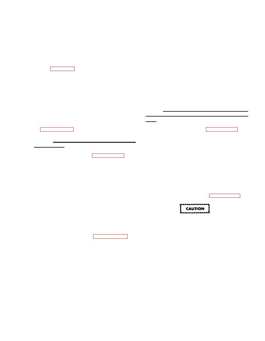
b. AC PHASE SELECT (1S9) and CUR-
disconnecting wires from more than
RENT SELECTOR (1S11) Switch Installa-
one terminal, make sure that wire
numbers are legible. If not, use
tion.
tape to identify wires. Refer to
(See figure 4-76.)
(1) Remove.
a. ENGINE
CONTROL
Switch
(1S1)
(a) Loosen two setscrews in
switch knob (1) and remove knob.
Installation.
(1) Remove.
(b) Unsolder all wires from
(See figure 4-75.)
terminal lugs on back of switch (4).
(a) Loosen two setscrews in
Use care not to shorten wires any more
than necessary.
switch knob (1) and remove knob.
(c) Remove nut (2), lockwasher
(b) Unsolder all wires from
(3), and switch (4).
terminal lugs on back of switch (4).
Use care not to shorten wires any more
(See figure 4-76.)
(2) Install.
than necessary.
(c) Remove nut (2), lockwasher
(3), and switch (4).
The nut against the switch body is
(d) Measure length of switch
the switch assembly nut (5). Do
shaft for reference.
not remove this nut.
(See figure 4-75.)
(2) Install.
(a) Remove nut (2) and lock-
(a) Using hacksaw, cut shaft of
washer (3) from replacement switch (4).
replacement switch to same length as
If two nuts remain on switch, remove
Do not remove switch assem-
shaft of old switch.
Remove any burrs
outer nut.
bly nut (5).
from shaft end.
(b) Remove nut (2) and lock-
(b) Install replacement switch
washer (3) from replacement switch (4).
(4) from back of panel, and secure with
lockwasher (3) and nut (2).
(c) Install replacement switch
(4) from back of panel, and secure with
(c) Solder all wires removed in
step (1) to solder lugs on switch.
lockwasher (3) and nut (2).
