
TM 55-1730-229-12
AG 320A0-OMM-000
TO 35C2-3-473-1
TM 1730-12/1
(b) Set height adjustment nut
connect all wires removed in step (1)
Replace lockwashers and terminal screws.
(5) on replacement switch shaft to same
position as adjustment nut on old
d. PRESS TO TEST Switch (1S4) In-
switch.
stallation.
(c) Install replacement switch
(See figure 4-78.)
(1) Remove.
(4) from back of panel.
(d) On MASTER SWITCH or PNEU-
(a) Pull switch spring (3) away
from switch bracket (2), and move switch
MATIC POWER switch, position switch
guard (3) on shaft of switch.
(1) in direction indicated to disengage
switch bracket from pushbutton flange
Slight rotation of switch may be
(e) Secure switch (4) to panel
(10).
necessary.
with lockwasher (2) and nut (1). One or
two threads on shaft of switch should be
visible from front of panel.
(b) Unsolder all wires (5) from
If not,
terminal posts (6) on switch. Use care
loosen retaining nut (1), reset adjust-
ment nut (5) as required, and tighten
not to shorten wires any more than nec-
essary.
retaining nut.
(f) Remove terminal screws and
(c) Remove nut (7), lockwasher
lockwashers from switch as required to
(8), and pushbutton (9).
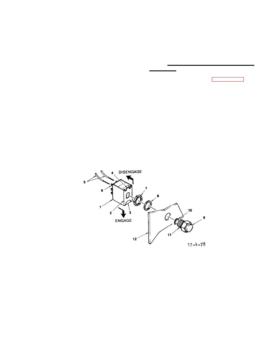
1.
SWITCH
7.
NUT
2.
BRACKET
8.
LOCKWASHER
3.
SPRING
9.
PUSHBUTTON
4.
ADJUSTMENT TAB
10.
FLANGE
5.
WIRE
11.
SEAL
6.
TERMINAL POSTS
12.
PANEL
Control Panel PRESS TO TEST Switches
