TM 55-1730-229-34
AG 320A0-MME-000
TO 35C2-3-473-2
TM 1730-34/1
HYDRAULIC MODULE PRESSURE TEST.
8-22.
Preparation for Hydraulic Test
(See figure 8-20.)
(1) Set test pressure supply pump
volume at 4 to 5 gpm.
(2) Set test pressure supply re-
lief valve at 5000 psi.
(3) Precharge accumulator in the
module being tested to 500 psi with ni-
trogen.
(4) Connect test circuit as shown
in figure 8-20.
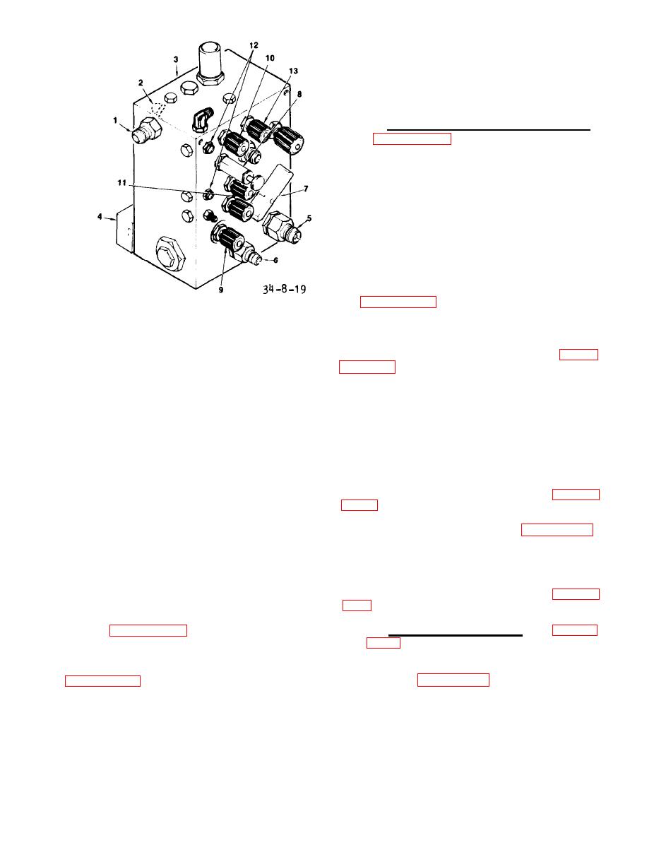
RETURN PORT
1.
INLET CONNECTION
2.
(5) Open return valve C.
MANIFOLD
3.
LOAD VALVE SOLENOID
4.
(6) Open RESERVOIR DRAIN (13, fig-
RETURN INLET
5.
PASS (9) valve on the control panel.
HIGH PRESSURE OUTLET
6.
RETURN BYPASS SELECTOR
7.
(7) Set the RESERVOIR selector
PRESSURE RELIEF VALVE
8.
Set the
valve to AIRCRAFT position.
HIGH PRESSURE BYPASS VALVE
9.
RETURN BYPASS (7) to BYPASS position.
RETURN BLEED VALVE
10.
HIGH PRESSURE BLEED VALVE
11.
(8) Start the test pressure supply
SIGHT GLASS
12.
RESERVOIR DRAIN VALVE
13.
pump.
Figure 8-19.
Manifold Controls/
(9) Open inlet valve A (figure
Fittings
Open the HIGH
module at 3 to 4 gpm.
PRESSURE BLEED valve (11, figure 8-19)
g. Open the HIGH PRESSURE BYPASS
and RETURN BLEED valve (10). Circulate
The pressure drop through
valve (9).
the manifold at gauge connected to HIGH
fluid until no evidence of air is noted
PRESSURE outlet (6) shall be a minimum
in the sight glasses (12) or flowrator.
of 500 psi.
(10) Close inlet valve A (figure
8-20) .
h. With the flow at 12 gpm energize
the load valve (4). Open shut-off valve
b. Low Pressure Leakage. (See fig-
no. 2 (figure 8-18) and check the back
The difference between the
ure 8-20.)
pressure.
back pressure in the RETURN port in the
OFF and BYPASS positions of selector (7,
(1) Close HIGH PRESSURE BLEED
valve (11 , figure 8-19) and RETURN BLEED
figure 8-19) should be a minimum of 55
valve (10). Set RESERVOIR selector on
psi. Drain manifold and plug or cap all
Close
module being tested to AGPU.
ports for storage or installation.
8-49


