
TM
55-1730-229-34
AG
320A0-MME-000
TO
35C2-3-473-2
TM
1730-34/1
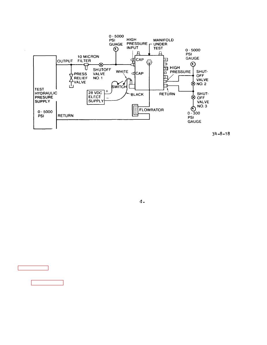
Figure 8-18.
Manifold Test Setup
e. Increase pressure to 150 psi and
c. With load valve solenoid (4) en-
hold two minutes. There shall be- no ex-
ergized, and all shut-off valves closed,
ternal leakage nor evidence of distor-
and relief valves set above 4500 psig,
tion.
apply 4500 psig to inlet connection (2).
Hold for two minutes. There shall be no
f. Reduce the pressure to zero and
evidence of external leakage, permanent
uncap res. 1 port. Increase pressure at
deformation, or subsequent malfunction.
the filter port to 3 psi and observe
leakage at the res. 1 port, with selec-
Repeat step c. with load valve
(4) de-energized.
tor set to AIRCRAFT. Leakage shall not
exceed 10 cc/min.
e. Open the HIGH PRESSURE BYPASS
e. Set the selector to AGPU.
Leak-
valve (9) and cap the return port (1).
Apply 1500 psi to the inlet connection
age shall not exceed 10 cc/rein.
(2) and hold two minutes. There should
h. Drain unit, drip dry, and cap
be no evidence of external leakage, per-
ports.
manent deformation, or subsequent mal-
function in the low pressure circuit.
8-21. MANIFOLD ASSEMBLY PRESSURE TEST.
a. Connect fluid source as shown in
f. Set PRESSURE RELIEF valve (8) at
3700 psi. Crack and reseat the PRESSURE
RELIEF valve (8) a few times to observe
b. Open HIGH PRESSURE BLEED valve
Check unit for external
function.
(11, figure 8-19) and RETURN BLEED valve
leaks. Energize and reenergize the load
(10) to remove air from system, and
valve (4) a minimum of three times and
observe sight glasses.
Close bleed
by observation verify 0.10 second mini-
valves.
mum time delay.
8-48
