
TM
55-1730-229-12
AG
320A0-OMM-000
TO
35C2-3-473-1
TM
1730-12/1
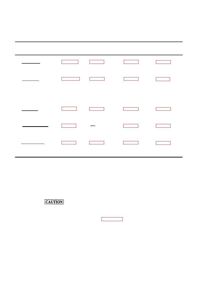
4. Power
2. Load
3. Pre Power
5. Remove
1. Desired Outputs
Connections
Application
Application
Power Steps
Steps
Steps
Steps
a. AC Power
Steps (1)
Steps (1) and
Steps (3)
Steps (8)
through (10)
(2)
through (6)
through (4)
b. DC Power
(in combination
Steps (1)
Steps (1) and
Step (8), then
Step (3)
with AC Power)
set BATTERY
through (4)
(2)
OUTPUT switch
to OFF, and
Step (10)
c. DC Power
(No AC Power)
Steps (3)
Steps (1) and
Steps (1)
Steps (8)
through (6)
through(10)
through (4)
(2)
d. Pneumatic Power
Steps (1) and
Steps (1)
Steps (4)
(2)
through (5)
through (7)
e. Hydraulic Power
Steps (1)
Steps (1)
steps (22)
Steps (24)
and (23)
through (17)
through (21)
through (28)
(4) On dc generator, set current limit selector
(7) Observe following start duty cycle for AGPU:
(if applicable) to maximum position.
(a) Two consecutive unsuccessful start attempts
(5) Start dc generator.
for a maximum of 15 seconds each are allowed.
(6) On dc generator, set dc power output
(b) After two unsuccessful start attempts, a
switch to on position.
minimum of 20 minutes off time is required. After 20
minutes, two additional 15 second start attempts may be
made consecutively. After this, 40 minutes off time is
required before any additional attempts can be made.
Observe the following AGPU starter
duty cycle when starting AGPU from a
(8) On AGPU, perform Start Procedure as outlined
dc generator, otherwise AGPU starter
will overheat.
2-36
