
TM 55-1730-229-34
AG 320A0-MME-000
TO 35C2-3-473-2
TM 1730-34/1
Table 2-2.
Direct/General Support Troubleshooting (continued)
MALFUNCTION
TEST OR INSPECTION
CORRECTIVE ACTION
a. If continuity, disassemble module and replace the high pres-
sure filter (27, figure 8-14). Perform steps a. through ae.
of paragraph 8-16. Reconnect wires to TB2-4.
If no continuity, do step 2.
b.
Step 2.
Check continuity between TB3-1 and the loose end of wire C117A16.
a. If continuity, disassemble module and replace the low pres-
sure filter (22, figure 8-14). Perform steps a. through ad.
of paragraph 8-16. Reconnect wires to TB2-4.
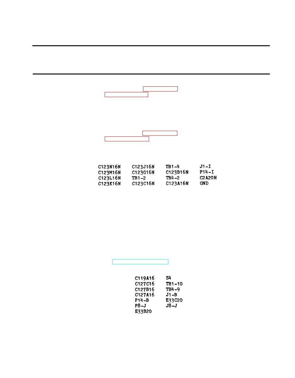
If no continuity, check for short between-REPLACE FILTER
b.
light and ground. The wires and connecting points are:
2.
CANNOT APPLY HYDRAULIC PRESSURE TO AIRCRAFT.
Step 1. Check dual manifold BYPASS/FLUSH valve position. If valve is open,
close valve. If problem is not corrected, continue with step 2.
Step 2. Remove hydraulic module front panel assembly. With system operating
in hydraulic mode, check for +24 vdc between TB2-3 and TB2-10
(ground) (see FO-9). Shut unit down and disconnect battery.
a. If +24 vdc was present, go to step 3.
If no voltage was present, check OUTPUT switch (paragraph
b.
4-90, TM 55-1730-229-12) and wiring for open condition. The
wires and connecting points are:
Replace switch or wiring as necessary and verify operation.
2-3
