
TM
55-1730-229-34
AG
320A0-MME-000
TO
35C2-3-473-2
TM
1730-34/1
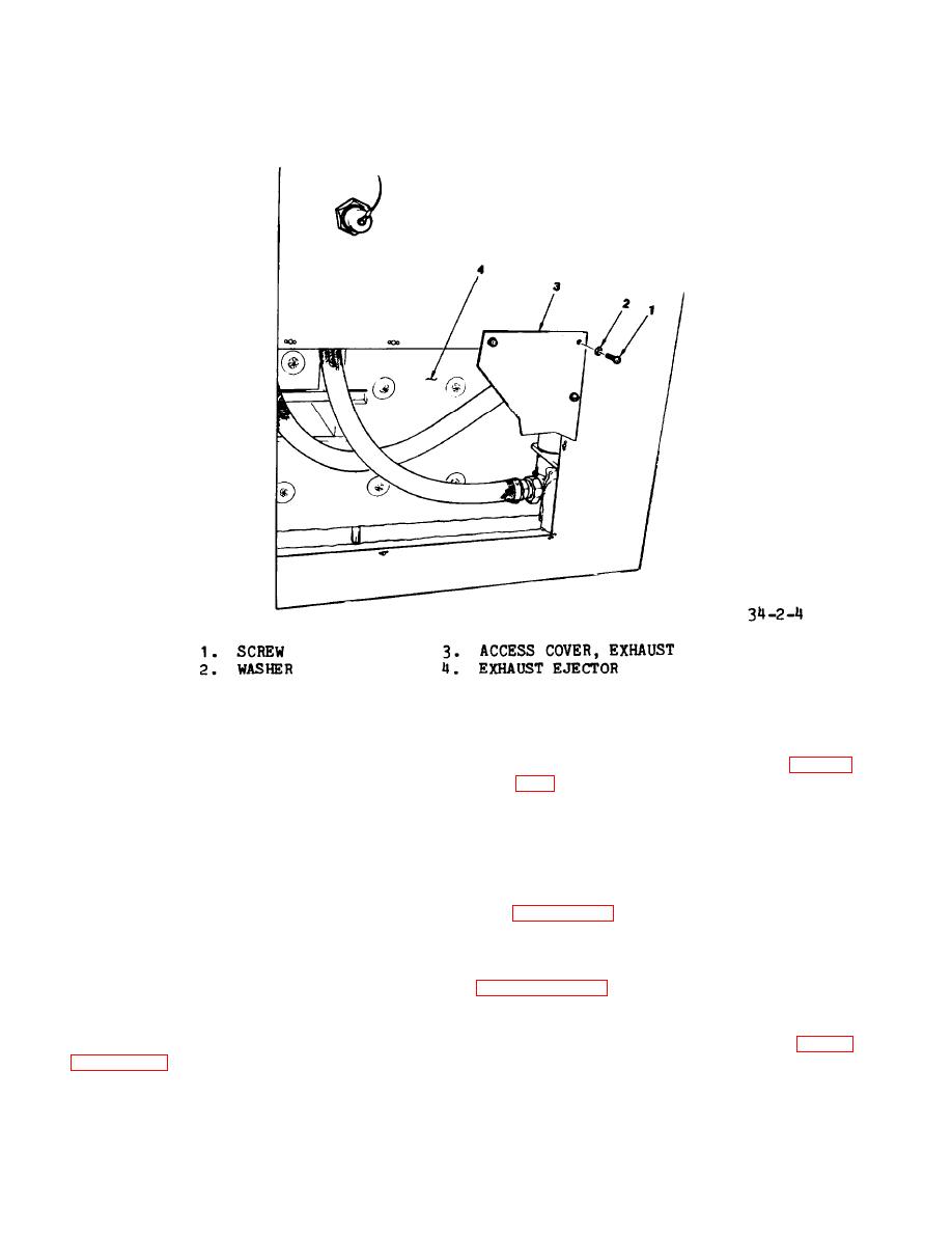
Figure 2-4.
Exhaust Ejector Access
(4) Align inlet tube (7) with en-
(7) Attach pneumatic hose (2, fig-
gine exhaust and install V-band coupling
ure 2-2) to elbow (3) with hose clamp
(5). Install nut (6) and tighten.
(l).
NOTE
(8) Install elbow (3) on exhaust
ejector and secure with nut (4).
Add or remove washers (12) if nec-
(9) Replace exhaust access cover
essary to align exhaust ejector
inlet tube with engine exhaust.
(3, figure 2-4) using twelve screws (1),
and washers (2).
(10) Install hydraulic module,
(5) Install twelve nuts (8) and
lockwashers (9) and tighten on studs
(10).
2-10. REMOVAL AND INSTALLATION OF
ENGINE/GENERATOR/HYDRAULIC PUMP. Fig-
(6) Install ejector drain tube (4,
figure 2-3). Replace cover (3) and in-
ure 2-5 shows an outline view of the
stall screws (1), and washers (2)-.
engine and generator from the right side
2-38
