
TM 55-1730-229-12
TO 35C2-3-473-1
(3) Remove DC cable from storage
b.
DC Power Application.
compartment on rear left side of AGPU.
(1) Set aircraft DC load control
(4) Connect DC cable to connector
switches to OFF.
on aircraft.
DC
Power
Application
-
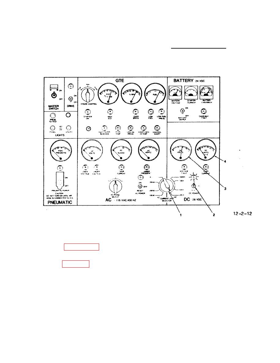
Control Panel Functions
CAUTION
(2)
Set CURRENT LIMIT SELECTOR
switch (1, figure 2-12) set to desired
The 83-360D does not monitor or
DC range. On the 83-360D, DC may be sup-
regulate the DC output of the TRU.
plied with the CURRENT LIMIT SELECTOR
The TRU output is not protected from
switch (1, Fig. 2-12) at any of the AC
an overload. When operating at high
setting.
DC output the DC AMPS meter and the
DC VER CURRENT light must be closely
(3)
Set DC POWER switch (2) to ON
monitored to protect the TRU from overload.
(check that green indicator light illu-
minates).
NOTE
(4)
Check that DC VOLTS meter (3)
If an overload or malfunction oc-
reads in green range.
curs and DC power is automatically
shutdown, observe DC malfunction
(5)
Set aircraft DC load control
indicator lights. Record any
switches to ON.
lights illuminated before setting
(6)
Observe that DC AMPS meter
DC POWER to RESET, or MASTER SWITCH
(4) does not read in red range. On the
to OFF.
83-360D, insure that the DC AMPS meter
(7) Remove DC power from aircraft
(4) does not read above 350 AMPS except
by performing steps (8) through (10).
during aircraft starting (or slave start
of another AGPU.
