TM 55-1730-229-12
EQUIPMENT CONVERSION.
bracket (7) inside engine compartment (8) by removing
NOTE
four bolts (11).
If hydraulic power is not required for an ex-
(5) Remove drain tube (6) from fitting (10) on
tended period of time, the pump should be
hydraulic pump (4).
disconnected from the GTE. This is done by
installing a spacer between the hydraulic pump
(6)
Lift drain tube (6) up and out of grommet
and the engine/gearcase pad. This discon-
(15).
nects the pump driveshaft from the gearcase
output-saving wear on pump and reducing load
(7) Support hydraulic pump and remove four
on engine.
nuts (3, figure 4-1) and washers (2) that secure pump
on gearcase pad (6).
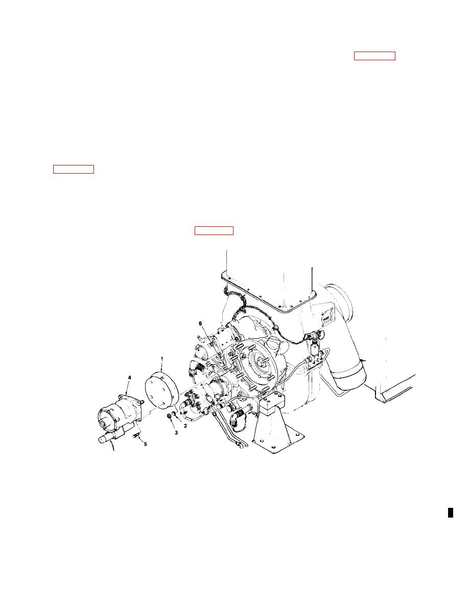
a. Installation of Hydraulic Pump Spacer. (See
(8) Move hydraulic pump (4) back approxi-
mately four inches.
(1)
Disconnect battery connector from battery.
(2)
Open engine access door.
(3) Remove DC cable from storage compart-
ment and remove hydraulic access cover (figure 4-6).
5. BOLT
1. SPACER
3. NUT
2. WASHER
4. HYDRAULIC PUMP
6. GEARCASE PAD
(9) Insert spacer (1) between hydraulic pump
(10) Install four nuts (3) and washers (2) that
(4) and gearcase pad (6). Ensure that flat side of spacer
were removed in step (7). This will attach spacer to
(1) is against the gearcase pad (6).
gearcase pad.


