
TM
55-1730-229-12
AC
320A0-OMM-000
TO
35C2-3-473-1
TM
1730-12/1
Table 4-2.
Organizational Troubleshooting (continued)
MALFUNCTION
TEST OR INSPECTION
CORRECTIVE ACTION
(continued)
57.
Step 1.
Note AC POWER ON indicator and set AC POWER switch off.
If AC POWER ON indicator was off (before AC POWER switch was set
to off), go to step 2 of malfunction 56. If not continue with
step 2 below.
Step 2.
Test ac contactor K1 (malfunction 95).
a. Replace contactor if defective (paragraph 4-53), and perform
operational check.
b. If contactor tests good, continue with step 3.
Test CURRENT LIMIT SELECTOR switch 1S11 (malfunction 79).
Step 3.
a.
Replace switch if defective (paragraph 4-104.b), and Perform
operational check.
b.
If switch tests good, do step 4.
Step 4.
Remove battery charger access cover. Disconnect main harness
connector P7 from control panel J7, and disconnect harness connector
P12 (36, figure 4-38) from GCU. Check for continuity between the
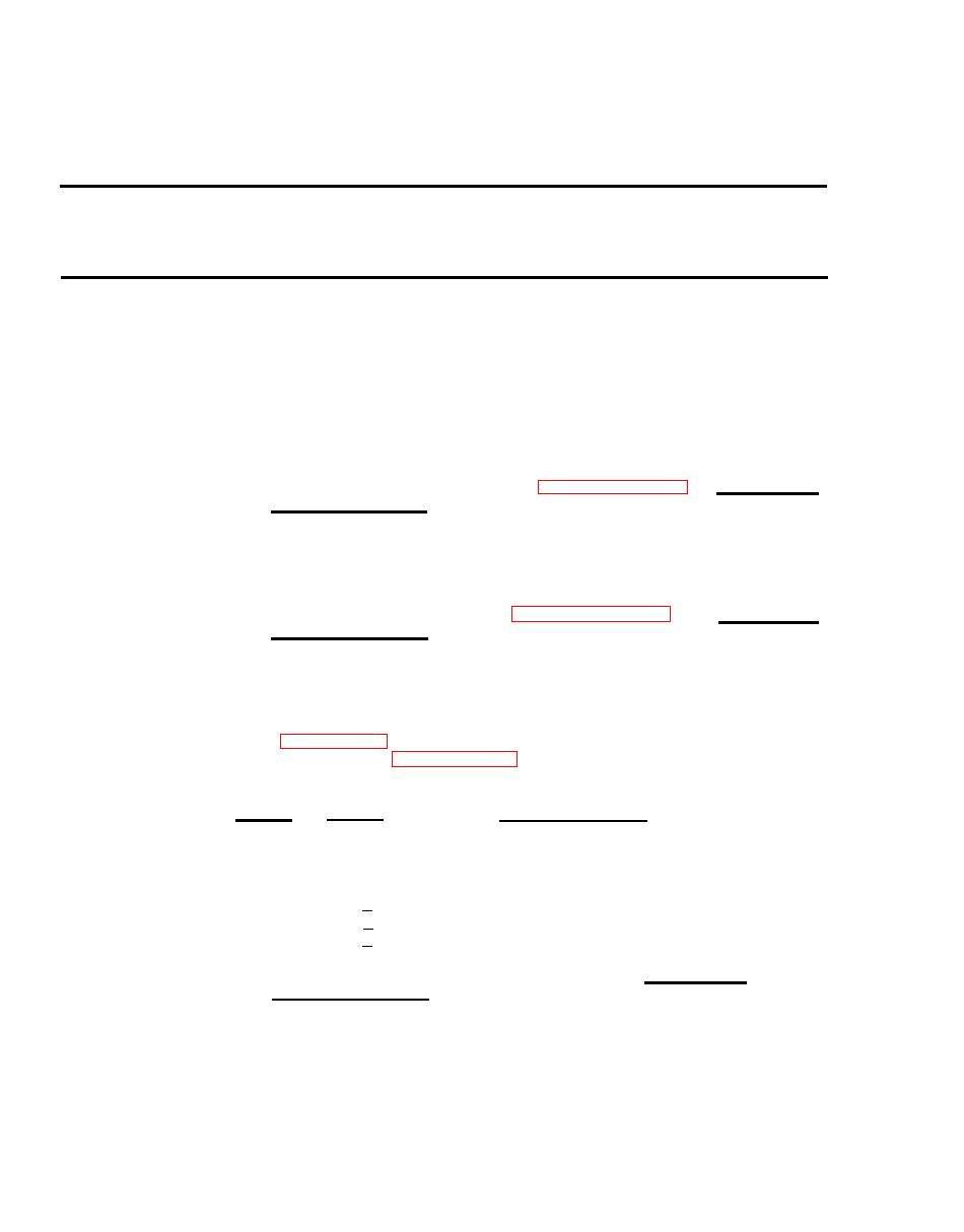
following points (see FO-6 sheet 2):
Check continuity
If no continuity,
From
To
replace wire no.
1S11B-1
X58B20
J7-(-)
1S11B-2
X57B20
57-(+)
1S11B-3
J7-C
X56B20
P12-S
X58A20
P7-(-)
P12-R
P7-(+)
X57A20
P7-C
P12-Q
X56A20
a.
If no continuity, replace indicated wire and perform
operational check.
b.
If all continuity checks good, do step 5.
4-88
