
TM 55-1730-229-12
AG 320A0-OMM-000
TO 35C2-3-473-1
TM 1730-12/1
6.
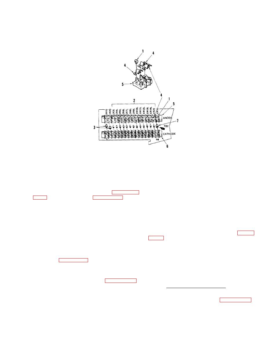
CATHODE TERMINAL BOARD
1.
4.
JUMPER
TERMINAL SCREW
2.
ANODE TERMINAL BOARD
7.
DIODE MR752
DIODE 1N5061
5.
3.
DIODE MR756
(b) If removing TB3 anode (4) or
(2) Lower control panel (paragraph
cathode (5), tag and disconnect all com-
ponents from TB.
(8 or 9), or TB2 (10 or 11) is to be re-
moved.
(c) Remove screws (1) and TB (2,
3, 4, or 5).
(3) Disconnect control panel sup-
port cable and lower control panel onto
(6) Remove TB1 Anode, TB1 Cathode,
access door if TB1 (8 or 9) or TB2 (10
TB2 Anode, or TB2 Cathode. (See figure
or 11) is to be removed.
(4)
If TB1 (8 or 9), TB2 (10 or
(a) Tag and remove all Wires
11), TB3
(4 or 5), or TB4 (3) is to be
from TB1 anode (8), TB1 cathode (9), TB2
removed,
remove battery charger access
cathode (10), or TB2 anode (11).
cover (5,
(b) Remove nuts (6), screws (7),
and TB (8, 9, 10, or 11).
(5) Remove Ground TB, TB3 Anode,
TB3 Cathode, or TB4. (See figure 4-20).
g. Install Terminal Boards.
(a) Tag and remove all wires
(1) Install Ground TB, TB3 Anode,
from ground TB (2), TB4 (3), TB3 anode
TB3 Cathode, or TB4. (See figure 4-20).
(4), or TB3 cathode (5).
